WIT Standard Communication Protocol
WIT Standard Communication Protocol
Instructions for Command:
Command
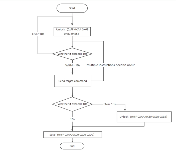
The serial port sending command must be completed within 10S, otherwise it will be automatically locked. To avoid this situation, please do the following steps first.
Enter the unlock command(0XFF 0XAA 0X69 0X88 0XB5,0X means hexadecimal )
Enter the command that needs to modify or read the data
Save command(0XFF 0XAA 0X00 0X00 0X00)
Register
ADDR (Hex) | ADDR (Dec) | REGISTER NAME | FUNCTION | SERIAL I/F | Bit15 | Bit14 | Bit13 | Bit12 | Bit11 | Bit10 | Bit9 | Bit8 | Bit7 | Bit6 | Bit5 | Bit4 | Bit3 | Bit2 | Bit1 | Bit0 |
00 | 00 | SAVE | Save/Reboot/Reset | R/W | SAVE[15:0] | |||||||||||||||
01 | 01 | CALSW | Calibretion Mode | R/W | CALSW[3:0] | |||||||||||||||
02 | 02 | RSW | Output Content | R/W | GSA | QUATER | VELOCITY | GPS | PRESS | PORT | MAG | ANGLE | GYRO | ACC | TIME | |||||
03 | 03 | RRATE | Output rate | R/W | RRATE[3:0] | |||||||||||||||
04 | 04 | BAUD | Baud rate | R/W | BAUD[3:0] | |||||||||||||||
05 | 05 | AXOFFSET | Acceleration X bias | R/W | AXOFFSET[15:0] | |||||||||||||||
06 | 06 | AYOFFSET | Acceleration Y bias | R/W | AYOFFSET[15:0] | |||||||||||||||
07 | 07 | AZOFFSET | Acceleration Z bias | R/W | AZOFFSET[15:0] | |||||||||||||||
08 | 08 | GXOFFSET | Angular velocity X bias | R/W | GXOFFSET[15:0] | |||||||||||||||
09 | 09 | GYOFFSET | Angular velocity Y bias | R/W | GYOFFSET[15:0] | |||||||||||||||
0A | 10 | GZOFFSET | Angular velocity Z bias | R/W | GZOFFSET[15:0] | |||||||||||||||
0B | 11 | HXOFFSET | Magnetic field X bias | R/W | HXOFFSET[15:0] | |||||||||||||||
0C | 12 | HYOFFSET | Magnetic field Y bias | R/W | HYOFFSET[15:0] | |||||||||||||||
0D | 13 | HZOFFSET | Magnetic field Z bias | R/W | HZOFFSET[15:0] | |||||||||||||||
0E | 14 | D0MODE | D0 Pin Mode | R/W | D0MODE[3:0] | |||||||||||||||
0F | 15 | D1MODE | D1 Pin Mode | R/W | D1MODE[3:0] | |||||||||||||||
10 | 16 | D2MODE | D2 Pin Mode | R/W | D2MODE[3:0] | |||||||||||||||
11 | 17 | D3MODE | D3 Pin Mode | R/W | D3MODE[3:0] | |||||||||||||||
1A | 26 | IICADDR | Device address | R/W | IICADDR[7:0] | |||||||||||||||
1B | 27 | LEDOFF | Turn off LED light | R/W | LEDOFF | |||||||||||||||
1C | 28 | MAGRANGX | Magnetic field X calibration range | R/W | MAGRANGX[15:0] | |||||||||||||||
1D | 29 | MAGRANGY | Magnetic field Y calibration range | R/W | MAGRANGY[15:0] | |||||||||||||||
1E | 30 | MAGRANGZ | Magnetic field Z calibration range | R/W | MAGRANGZ[15:0] | |||||||||||||||
1F | 31 | BANDWIDTH | Bandwidth | R/W | BANDWIDTH[3:0] | |||||||||||||||
20 | 32 | GYRORANGE | Gyro range | R/W | GYRORANGE[3:0] | |||||||||||||||
21 | 33 | ACCRANGE | Acceleration range | R/W | ACCRANGE[3:0] | |||||||||||||||
22 | 34 | SLEEP | Sleep | R/W | SLEEP | |||||||||||||||
23 | 35 | ORIENT | Installation direction | R/W | ORIENT | |||||||||||||||
24 | 36 | AXIS6 | Algorithm | R/W | AXIS6 | |||||||||||||||
25 | 37 | FILTK | Dynamic filtering | R/W | FILTK[15:0] | |||||||||||||||
26 | 38 | GPSBAUD | GPS Baud rate | R/W | GPSBAUD[3:0] | |||||||||||||||
27 | 39 | READADDR | Read register | R/W | READADDR[7:0] | |||||||||||||||
2A | 42 | ACCFILT | Acceleration filtering | R/W | ACCFILT[15:0] | |||||||||||||||
2D | 45 | POWONSEND | command start | R/W | POWONSEND[3:0] | |||||||||||||||
2E | 46 | VERSION | Version number | R | VERSION[15:0] | |||||||||||||||
30 | 48 | YYMM | Year/Mouth | R/W | MOUTH[15:8] | YEAR[7:0] | ||||||||||||||
31 | 49 | DDHH | Hour/Day | R/W | HOUR[15:8] | DAY[7:0] | ||||||||||||||
32 | 50 | MMSS | Minutes/Seconds | R/W | SECONDS[15:8] | MINUTE[7:0] | ||||||||||||||
33 | 51 | MS | millisecond | R/W | MS[15:0] | |||||||||||||||
34 | 52 | AX | Acceleration X | R | AX[15:0] | |||||||||||||||
35 | 53 | AY | Acceleration Y | R | AY[15:0] | |||||||||||||||
36 | 54 | AZ | Acceleration Z | R | AZ[15:0] | |||||||||||||||
37 | 55 | GX | Angular velocity X | R | GX[15:0] | |||||||||||||||
38 | 56 | GY | Angular velocity Y | R | GY[15:0] | |||||||||||||||
39 | 57 | GZ | Angular velocity Z | R | GZ[15:0] | |||||||||||||||
3A | 58 | HX | Magnetic field X | R | HX[15:0] | |||||||||||||||
3B | 59 | HY | Magnetic field Y | R | HY[15:0] | |||||||||||||||
3C | 60 | HZ | Magnetic field Z | R | HZ[15:0] | |||||||||||||||
3D | 61 | Roll | Roll | R | Roll[15:0] | |||||||||||||||
3E | 62 | Pitch | Pitch angle | R | Pitch[15:0] | |||||||||||||||
3F | 63 | Yaw | Heading | R | Yaw[15:0] | |||||||||||||||
40 | 64 | TEMP | Temperature | R | TEMP[15:0] | |||||||||||||||
41 | 65 | D0Status | D0 pin state | R | D0Status[15:0] | |||||||||||||||
42 | 66 | D1Status | D1pin state | R | D1Status[15:0] | |||||||||||||||
43 | 67 | D2Status | D2 pin state | R | D2Status[15:0] | |||||||||||||||
44 | 68 | D3Status | D3 pin state | R | D3Status[15:0] | |||||||||||||||
45 | 69 | PressureL | Air pressure low 16 bits | R | PressureL[15:0] | |||||||||||||||
46 | 70 | PressureH | Air pressure high16 bits | R | PressureH[15:0] | |||||||||||||||
47 | 71 | HeightL | Height lower 16 bits | R | HeightL[15:0] | |||||||||||||||
48 | 72 | HeightH | Height high 16 bits | R | HeightH[15:0] | |||||||||||||||
49 | 73 | LonL | Longitude lower 16 bits | R | LonL[15:0] | |||||||||||||||
4A | 74 | LonH | Longitude high 16 bits | R | LonH[15:0] | |||||||||||||||
4B | 75 | LatL | Latitude lower 16 bits | R | LatL[15:0] | |||||||||||||||
4C | 76 | LatH | Latitude high 16 bits | R | LatH[15:0] | |||||||||||||||
4D | 77 | GPSHeight | GPS Altitute | R | GPSHeight[15:0] | |||||||||||||||
4E | 78 | GPSYAW | GPS Heading | R | GPSYAW[15:0] | |||||||||||||||
4F | 79 | GPSVL | GPS round speed low 16 bits | R | GPSVL[15:0] | |||||||||||||||
50 | 80 | GPSVH | GPS ground speed high 16 bits | R | GPSVH[15:0] | |||||||||||||||
51 | 81 | q0 | Quaternion 0 | R | q0[15:0] | |||||||||||||||
52 | 82 | q1 | Quaternion1 | R | q1[15:0] | |||||||||||||||
53 | 83 | q2 | Quaternion2 | R | q2[15:0] | |||||||||||||||
54 | 84 | q3 | Quaternion3 | R | q3[15:0] | |||||||||||||||
55 | 85 | SVNUM | Number of satellites | R | SVNUM[15:0] | |||||||||||||||
56 | 86 | PDOP | Position accuracy | R | PDOP[15:0] | |||||||||||||||
57 | 87 | HDOP | Horizontal accuracy | R | HDOP[15:0] | |||||||||||||||
58 | 88 | VDOP | Vertical accuracy | R | VDOP[15:0] | |||||||||||||||
59 | 89 | DELAYT | Alarm delay | R/W | DELAYT[15:0] | |||||||||||||||
5A | 90 | XMIN | X-axis angle alarm min. | R/W | XMIN[15:0] | |||||||||||||||
5B | 91 | XMAX | X-axis angle alarm max. | R/W | XMAX[15:0] | |||||||||||||||
5C | 92 | BATVAL | Supply voltage | R | BATVAL[15:0] | |||||||||||||||
5D | 93 | ALARMPIN | Alarm Pin Mapping | R/W | X-ALARM[15:12] | X+ALARM[11:8] | Y-ALARM[7:4] | Y+ALARM[3:0] | ||||||||||||
5E | 94 | YMIN | Y-axis alarm min. | R/W | YMIN[15:0] | |||||||||||||||
5F | 95 | YMAX | Y-axis alarm max. | R/W | YMAX[15:0] | |||||||||||||||
61 | 97 | GYROCALITHR | Gyro Still Threshold | R/W | GYROCALITHR[15:0] | |||||||||||||||
62 | 98 | ALARMLEVEL | Angle alarm level | R/W | ALARMLEVEL[3:0] | |||||||||||||||
63 | 99 | GYROCALTIME | Gyro auto calibration time | R/W | GYROCALTIME[15:0] | |||||||||||||||
68 | 104 | TRIGTIME | Alarm continuous trigger time | R/W | TRIGTIME[15:0] | |||||||||||||||
69 | 105 | KEY | Unlock | R/W | KEY[15:0] | |||||||||||||||
6A | 106 | WERROR | Gyro change | R | WERROR[15:0] | |||||||||||||||
6B | 107 | TIMEZONE | GPSTimezone | R/W | TIMEZONE[7:0] | |||||||||||||||
6E | 110 | WZTIME | Angular velocity continuous rest time | R/W | WZTIME[15:0] | |||||||||||||||
6F | 111 | WZSTATIC | Angular velocity integral threshold | R/W | WZSTATIC[15:0] | |||||||||||||||
74 | 116 | MODDELAY | 485 data response delay | R/W | ||||||||||||||||
79 | 121 | XREFROLL | Roll angle zero reference value | R | XREFROLL[15:0] | |||||||||||||||
7A | 122 | YREFPITCH | Pitch angle zero reference value | R | YREFPITCH[15:0] | |||||||||||||||
7F | 127 | NUMBERID1 | Device No1-2 | R | ID2[15:8] | ID1[7:0] | ||||||||||||||
80 | 128 | NUMBERID2 | Device No3-4 | R | ID4[15:8] | ID3[7:0] | ||||||||||||||
81 | 129 | NUMBERID3 | Device No5-6 | R | ID6[15:8] | ID5[7:0] | ||||||||||||||
82 | 130 | NUMBERID4 | Device No7-8 | R | ID8[15:8] | ID7[7:0] | ||||||||||||||
83 | 131 | NUMBERID5 | Device No9-10 | R | ID10[15:8] | ID9[7:0] | ||||||||||||||
84 | 132 | NUMBERID6 | Device No11-12 | R | ID12[15:8] | ID11[7:0] |
Protocol Format
Read
The Data is sent in hexadecimal, not ASCII.
Each data is transmitted in sequence by low byte and high byte, and the two are combined into a signed short type of data. For example, for data DATA1, DATA1L is the low byte and DATA1H is the high byte. The conversion method is as follows:
Suppose DATA1 is the actual data, DATA1H is its high-byte part, DATA1L is its low-byte part.
Then: DATA1=(short)((short)DATA1H<<8|DATA1L). It must be noted here that DATA1H needs to be coerced into a signed short type of data before shifting, and the data type of DATA1 is also a signed short type, so that it can represent negative numbers.
Protocol header | Data content | Data lower 8 bits | Data higher 8 bits | Data lower 8 bits | Data higher 8 bits | Data lower 8 bits | Data higher 8 bits | Data lower 8 bits | Data higher 8 bits | SUMCRC |
0x55 | TYPE【1】 | DATA1L[7:0] | DATA1H[15:8] | DATA2L[7:0] | DATA2H[15:8] | DATA3L[7:0] | DATA3H[15:8] | DATA4L[7:0] | DATA4H[15:8] | SUMCRC【2】 |
【1】TYPE(Data content):
TYPE | Remark |
0x50 | Time |
0x51 | Acceleration |
0x52 | Angular velocity |
0x53 | Angle |
0x54 | Magnetic field |
0x55 | Port |
0x56 | Barometric altitude |
0x57 | Latitude and Longitude |
0x58 | ground speed |
0x59 | Quaternion |
0x5A | GPS Location accuracy |
0x5F | Read |
【2】SUMCRC(Data and calibration):
SUMCRC=0x55+TYPE+DATA1L+DATA1H+DATA2L+DATA2H+DATA3L+DATA3H+DATA4L+DATA4H
SUMCRC is a char type, taking the lower 8 bits of the checksum
Time Output
0x55 | 0x50 | YY | MM | DD | HH | MN | SS | MSL | MSH | SUM |
Name | Describe | Remark | ||||||||
YY | Year | |||||||||
MM | Mouth | |||||||||
DD | Day | |||||||||
HH | Hour | |||||||||
MN | Minute | |||||||||
SS | Seconds | |||||||||
MSL | MS lower 8 bits | Millisecond calculation formula: milliseconds=((MSH<<8)|MSL) | ||||||||
MSH | MS higher 8 bits | |||||||||
SUM | Checksum | SUM=0x55+0x50+YY+MM+DD+HH+MN+SS+MSL+MSH |
Acceleration Output
0x55 | 0x51 | AxL | AxH | AyL | AyH | AzL | AzH | TL | TH | SUM |
Name | Description | Remark | ||||||||
AxL | Acceleration X low 8 bits | Acceleration X=((AxH<<8)|AxL)/32768*16g (g is the acceleration of gravity, preferably 9.8m/s2) | ||||||||
AxH | Acceleration X high 8 bits | |||||||||
AyL | Acceleration Y low 8 bits | Acceleration Y=((AyH<<8)|AyL)/32768*16g (g is the acceleration of gravity, preferably 9.8m/s2) | ||||||||
AyH | Acceleration Yhigh 8 bits | |||||||||
AzL | Acceleration Z low 8 bits | Acceleration Z=((AzH<<8)|AzL)/32768*16g (g is the acceleration of gravity, preferably 9.8m/s2) | ||||||||
AzH | Acceleration Z high 8 bits | |||||||||
TL | 8-bit lower temperature | Temperature calculation formula: Temperature=((TH<<8)|TL) /100 ℃ | ||||||||
TH | 8-bit higher temperature | |||||||||
SUM | Check sum | SUM=0x55+0x51+AxL+AxH+AyL+AyH+AzL+AzH+TL+Th |
Angular velocity output
0x55 | 0x52 | WxL | WxH | WyL | WyH | WzL | WzH | VolL | VolH | SUM |
Name | Description | Remark | ||||||||
WxL | Angular velocity X low 8 bits | Angular velocity X=((WxH<<8)|WxL)/32768*2000°/s | ||||||||
WxH | Angular velocity X high 8 bits | |||||||||
WyL | Angular velocity Y low 8 bits | Angular velocity Y=((WyH<<8)|WyL)/32768*2000°/s | ||||||||
WyH | Angular velocity Y high 8 bits | |||||||||
WzL | Angular velocity Z low 8 bits | Angular velocity Z=((WzH<<8)|WzL)/32768*2000°/s | ||||||||
WzH | Angular velocity Z high 8 bits | |||||||||
VolL | Voltage lower 8 bits | (Non-Bluetooth products, the data is invalid) Voltage calculation formula: Voltage=((VolH<<8)|VolL) /100 ℃ | ||||||||
VolH | Voltage higher 8 bits | |||||||||
SUM | Check sum | SUM=0x55+0x52+WxL+WxH+WyL+WyH+WzL+WzH+VolH+VolL |
Angular output
0x55 | 0x53 | RollL | RollH | PitchL | PitchH | YawL | YawH | VL | VH | SUM |
Name | Description | Remark | ||||||||
RollL | Roll angle X lower 8 bits | Roll angle X=((RollH<<8)|RollL)/32768*180(°) | ||||||||
RollH | Roll angle X highter 8 bits | |||||||||
PitchL | Pitch angle Y low 8 bits | Pitch angleY=((PitchH<<8)|PitchL)/32768*180(°) | ||||||||
PitchH | Pitch angle Y high 8 bits | |||||||||
YawL | Yaw angle Z lower8 bits | Yaw angleZ=((YawH<<8)|YawL)/32768*180(°) | ||||||||
YawH | Yaw angle Z higher 8 bits | |||||||||
VL | Version number lower 8 bits | Version number calculation formula: Version number=(VH<<8)|VL | ||||||||
VH | Version number higher 8 bits | |||||||||
SUM | Check Sum | SUM=0x55+0x53+RollH+RollL+PitchH+PitchL+YawH+YawL+VH+VL |
Magnetic field output
0x55 | 0x54 | HxL | HxH | HyL | HyH | HzL | HzH | TL | TH | SUM |
Name | Description | Remark | ||||||||
HxL | Magnetic field X lower 8 bits | Magnetic fieldX=((HxH<<8)|HxL) | ||||||||
HxH | Magnetic field X higher 8 bits | |||||||||
HyL | Magnetic field Y lower 8 bits | Magnetic fieldY=((HyH <<8)|HyL) | ||||||||
HyH | Magnetic fieldY higher 8 bits | |||||||||
HzL | Magnetic field Z lower 8 bits | Magnetic fieldZ=((HzH<<8)|HzL) | ||||||||
HzH | Magnetic field Z lower 8 bits | |||||||||
TL | 8-bit lower temperature | Temperature calculation formula: Temperature=((TH<<8)|TL) /100 ℃ | ||||||||
TH | 8-bit lhigher temperature | |||||||||
SUM | Check Sum | SUM=0x55+0x54+HxH+HxL+HyH+HyL+HzH+HzL+TH+TL |
Port status output
0x55 | 0x55 | D0L | D0H | D1L | D1H | D2L | D2H | D3L | D3H | SUM |
Name | Description | Remark | ||||||||
D0L | D0 status lower 8 bits | D0 status=((D0H<<8)|D0L) | ||||||||
D0H | D0 status higher 8 bits | |||||||||
D1L | D1 status lower 8 bits | D1status=((D1H<<8)|D1L) | ||||||||
D1H | D1 status higher 8 bits | |||||||||
D2L | D2 status lower 8 bits | D2 status=((D2H<<8)|D2L) | ||||||||
D2H | D2 status higher 8 bits | |||||||||
D3L | D3 status lower 8 bits | D3 status=((D3H<<8)|D3L) | ||||||||
D3H | D3 status higher 8 bits | |||||||||
SUM | Check Sum | SUM=0x55+0x54+D0L+D0H+D1L+D1H+D2L+D2H+D3L+D3H |
explanation:
● When the port mode is set to analog input, the port status data represents the analog voltage. The actual voltage is calculated according to the formula below:
U=DxStatus/1024*Uvcc
● Uvcc is the power supply voltage of the chip. Since there are LDOs on the chip, if the power supply voltage of the module is greater than 3.5V, Uvcc is 3.3V. If the module power supply voltage is less than 3.5V, Uvcc=pexplaower supply voltage -0.2V.
● When the port mode is set to digital input, the port status data indicates the digital level status of the port, high level is 1 and low level is 0.
● When the port mode is set to high-level output mode, the port status data is 1.
● When the port mode is set to low-level output mode, the port status data bit is 0.
Air pressure altitude output
0x55 | 0x56 | P0 | P1 | P2 | P3 | H0 | H1 | H2 | H3 | SUM |
Name | Description | Remark | ||||||||
P0 | Air pressure[7:0] | Air pressure[ | ||||||||
P1 | Air pressure[[15:8] | |||||||||
P2 | Air pressure[[23:16] | |||||||||
P3 | Air pressure[31:24] | |||||||||
H0 | Altitute[7:0] | Altitute | ||||||||
H1 | Altitute[15:8] | |||||||||
H2 | Altitute[23:16] | |||||||||
H3 | Altitute[31:24] | |||||||||
SUM | Check sum | SUM=0x55+0x56+P0+P1+P2+P3+H0+H1+H2+H3 |
Latitude and longitude
0x55 | 0x57 | Lon0 | Lon1 | Lon2 | Lon3 | Lat0 | Lat1 | Lat2 | Lat3 | SUM |
Name | Description | Remark | ||||||||
Lon0 | Longitude[7:0] | Longitude | ||||||||
Lon1 | Longitude[15:8] | |||||||||
Lon2 | Longitude[23:16] | |||||||||
Lon3 | Longitude[31:24] | |||||||||
Lat0 | Latitude[7:0] | Latitude | ||||||||
Lat1 | Latitude[15:8] | |||||||||
Lat2 | Latitude[23:16] | |||||||||
Lat3 | Latitude[31:24] | |||||||||
SUM | Checksum | SUM=0x55+0x57+Lon0+Lon1+Lon2+Lon3+Lat0+Lat1+Lat2+Lat3 |
Explanation:
The NMEA8013 standard stipulates that the longitude output format of GPS is dd mm.mmmmm (dd is degrees, mm.mmmmm is minutes), and the decimal point is removed from the output of longitude/latitude, so the degrees of longitude/latitude can be calculated as follows:
dd=Lon [31:0]/10000000;
dd=Lat [31:0]/10000000;
Longitude/latitude fraction calculation:
mm.mmmmm= (Lon [31:0] %10000000)/100000(% indicates the remainder operation)
mm.mmmmm= (Lat [31:0] %10000000)/100000(% indicates the remainder operation)
GPS data output
0x55 | 0x58 | GPS HeightL | GPS HeightH | GPS YawL | GPS YawH | GPSV0 | GPSV1 | GPSV2 | GPSV3 | SUM | |
Name | Description | Remark | |||||||||
GPS HeightL | GPS altitude[7:0] | GPS altitude=((GPSHeightH<<8)|GPSHeightL)/10(m) | |||||||||
GPS HeightH | GPS altitude[15:8] | ||||||||||
GPS YawL | GPS heading [7:0] | GPS heading =((GPSYawH<<8)|GPSYawL)/100(°) | |||||||||
GPS YawH | GPSheading [15:8] | ||||||||||
GPSV0 | GPS Ground Speed[7:0] | GPS Ground Speed | |||||||||
GPSV1 | GPS Ground Speed[15:8] | ||||||||||
GPSV2 | GPS Ground Speed[23:16] | ||||||||||
GPSV3 | GPS Ground Speed[31:24] | ||||||||||
SUM | Check sum | SUM=0x55+0x58+GPSHeightL+GPSHeightH+GPSYawL+GPSYawH+GPSV0+GPSV1+GPSV2+GPSV3 |
Quaternion output
0x55 | 0x59 | Q0L | Q0H | Q1L | Q1H | Q2L | Q2H | Q3L | Q3H | SUM |
Name | Description | Remark | ||||||||
Q0L | Q0 lower 8 bits | q0=((Q0H<<8) |Q0L)/32768 | ||||||||
Q0H | Q0 high 8 bits | |||||||||
Q1L | Q1 lower 8 bits | q1=((Q1H<<8) |Q1L)/32768 | ||||||||
Q1H | Q1 high 8 bits | |||||||||
Q2L | Q2 lower 8 bits | q2=((Q2H<<8) |Q2L)/32768 | ||||||||
Q2H | Q2 high 8 bits | |||||||||
Q3L | Q3 lower 8 bits | q3=((Q3H<<8)|Q3L)/32768 | ||||||||
Q3H | Q3 high 8 bits | |||||||||
SUM | Checksum | SUM=0x55+0x59+Q0L+Q0H+Q1L +Q1H +Q2L+Q2H+Q3L+Q3H |
GPS Positioning accuracy output
0x55 | 0x5A | SNL | SNH | PDOPL | PDOPH | HDOPL | HDOPH | VDOPL | VDOPH | SUM | |
Name | Description | Remark | |||||||||
SNL | Satellite number low 8 bits | GPSSatellite number=((SNH<<8) |SNL) | |||||||||
SNH | Satellite number high 8 bits | ||||||||||
PDOPL | Position accuracy low 8 bits | Position accuracy=((PDOPH<<8) |PDOPL)/100 | |||||||||
PDOPH | Position accuracy high 8 bits | ||||||||||
HDOPL | Horizontal precision low 8 bits | Horizontal precision=((HDOPH<<8) |HDOPL)/100 | |||||||||
HDOPH | Horizontal precision high 8 bits | ||||||||||
VDOPL | Vertical precision low 8 bits | Vertical precision =((VDOPH<<8)|VDOPL)/100 | |||||||||
VDOPH | Vertical precision high 8 bits | ||||||||||
SUM | Checksum | SUM=0x55+0x5A+SNL+SNH+PDOPL+PDOPH+HDOPL+HDOPH+VDOPL+VDOPH |
Read the return value of the register
Read the value of the register specified by the user, read REG1, then return the value of the 4 registers of REG1~REG4, the protocol must return 4 registers.
0x55 | 0x5F | REG1L | REG1H | REG2L | REG2H | REG3L | REG3H | REG4L | REG4H | SUM | |
Name | Description | Remark | |||||||||
REG1L | Register 1 low 8 bits | REG1[15:0]=((REG1H<<8)|REG1L) | |||||||||
REG1H | Register 1 high 8 bits | ||||||||||
REG2L | Register 2 low 8 bits | REG2[15:0]=((REG2H<<8)|REG2L) | |||||||||
REG2H | Register 2 high 8 bits | ||||||||||
REG3L | Register 3 low 8 bits | REG3[15:0]=((REG3H<<8)|REG3L) | |||||||||
REG3H | Register 3 high 8 bits | ||||||||||
REG4L | Register 4 low 8 bits | REG4[15:0]=((REG4H<<8)|REG4L) | |||||||||
REG5H | Register 4 high 8 bits | ||||||||||
SUM | Checksum | SUM=0x55+0x5F+REG1L+REG1H+REG2L+REG2H+REG3L+REG3H+REG4L+REG4H |
Example:
Read register "AXOFFSET", return:0x55 0x5F AXOFFSET [7:0] AXOFFSET [15:8] AYOFFSET [7:0] AYOFFSET [15:8] AZOFFSET [7:0] AZOFFSET [15:8] GXOFFSET [7:0] GXOFFSET [15:8] SUM
Write Format
The following data are all Hex codes in hexadecimal
All settings need to operate the unlock register first(KEY)
Head | Head | Register | Data lower 8 bits | Data high 8 bits |
0xFF | 0xAA | ADDR | DATAL[7:0] | DATAH[15:8] |
The data is sent in hexadecimal not ASCII.
Each data is divided into low byte and high byte and transmitted in turn, and the two are combined into a signed short data.
For example, DATA, DATAL is the low byte, DATAH is the high byte.
Conversion method: Assuming that DATA is the actual data, DATAH is its high-byte part, and DATAL is its low-byte part, then:DATA=(short)((short)DATAH<<8|DATAL)
DATAH must be cast to a signed short type before shifting, and the data type of DATA is also a signed short type, so that negative numbers can be represented.
Note:
There are three steps to perform the command write operation.
Step1. Unlock 0xFF 0XAA 0X69 0X88 0XB5
Step2. Send the command to be modified
Step3. Save 0xFF 0XAA 0X00 0X00 0X00
The flow chart is below.The data is sent in hexadecimal not ASCII.
Each data is divided into low byte and high byte and transmitted in turn, and the two are combined into a signed short data.
For example, DATA, DATAL is the low byte, DATAH is the high byte.
Conversion method: Assuming that DATA is the actual data, DATAH is its high-byte part, and DATAL is its low-byte part, then:DATA=(short)((short)DATAH<<8|DATAL)
DATAH must be cast to a signed short type before shifting, and the data type of DATA is also a signed short type, so that negative numbers can be represented.
Note:
There are three steps to perform the command write operation.
Step1. Unlock 0xFF 0XAA 0X69 0X88 0XB5
Step2. Send the command to be modified
Step3. Save 0xFF 0XAA 0X00 0X00 0X00
The flow chart is below.
SAVE(Save/restart/reset)
Register Name: SAVE Register Address: 0 (0x00) Read and write direction: R/W Default: 0x0000 | ||
Bit | NAME | FUNCTION |
15:0 | SAVE[15:0] | Save: 0x0000 Restart: 0x00FF Factory reset: 0x0001 |
Example:FF AA 00 FF 00(Restart) |
CALSW(Calibration mode)
Register Name: CALSW Register Address: 1 (0x01) Read and write direction: R/W Default: 0x0000 | ||
Bit | NAME | FUNCTION |
15:4 | ||
3:0 | CAL[3:0] | Set calibration mode: 0000(0x00): Normal working mode 0001(0x01): Automatic accelerometer calibration 0011(0x03): Height reset 0100(0x04): Set the heading angle to zero 0111(0x07): Magnetic Field Calibration (Spherical Fitting) 1000 (0x08): Set the angle reference 1001(0x09): Magnetic Field Calibration (Dual Plane Mode) |
Example:FF AA 01 04 00(Set heading angle to zero) |
RSW(Output content)
Register Name: RSW Register Address: 2 (0x02) Read and write direction: R/W Default: 0x001E | ||
Bit | NAME | FUNCTION |
15:11 | ||
10 | GSA (0x5A) | 0: off 1: on |
9 | QUATER (0x59) | 0: off 1: on |
8 | VELOCITY (0x58) | 0: off 1: on |
7 | GPS (0x57) | 0: off 1: on |
6 | PRESS (0x56) | 0: off 1: on |
5 | PORT (0x55) | 0: off 1: on |
4 | MAG (0x54) | 0: off 1: on |
3 | ANGLE (0x53) | 0: off 1: on |
2 | GYRO (0x52) | 0: off 1: on |
1 | ACC (0x51) | 0: off 1: on |
0 | TIME (0x50) | 0: off 1: on |
Example: FF AA 02 3E 00 (set to only output acceleration, angular velocity, angle, magnetic field, port state) |
RRATE (Output rate)
Register Name: RRATE Register Address: 3 (0x03) Read and write direction: R/W Default: 0x0006 | ||
Bit | NAME | FUNCTION |
15:4 | ||
3:0 | RRATE[3:0] | Set the output rate: 0001(0x01): 0.2Hz 0010(0x02): 0.5Hz 0011(0x03): 1Hz 0100(0x04): 2Hz 0101(0x05): 5Hz 0110(0x06): 10Hz 0111(0x07): 20Hz 1000(0x08): 50Hz 1001(0x09): 100Hz 1011(0x0B): 200Hz 1011(0x0C): single return 1100(0x0D): no return |
Example: FF AA 03 03 00 (set 1Hz output) Note: HWT906, WT931 can output 500Hz, 1000Hz FF AA 03 0C 00: 500HzFF AA 03 0D 00: 1000Hz FF AA 03 10 00 : single return |
BAUD(Serial baud rate)
Register Name: BAUD Register Address: 4 (0x04) Read and write direction: R/W Default: 0x0002 | ||
Bit | NAME | FUNCTION |
15:4 | ||
3:0 | BAUD[3:0] | Set the serial port baud rate: 0001(0x01): 4800bps 0010(0x02): 9600bps 0011(0x03): 19200bps 0100(0x04): 38400bps 0101(0x05): 57600bps 0110(0x06): 115200bps 0111(0x07): 230400bps 1000(0x08): 460800bps(Only supportsWT931/JY931/HWT606/HWT906) 1001(0x09): 921600bps(Only supportsWT931/JY931/HWT606/HWT906) |
Example:FF AA 04 06 00(Set serial port baud rate115200) |
AXOFFSET~HZOFFSET(Zero bias setting)
Register Name: AXOFFSET~HZOFFSET Register Address: 5~13 (0x05~0x0D) Read and write direction: R/W Default: 0x0000 | ||
Bit | NAME | FUNCTION |
15:0 | AXOFFSET[15:0] | Acceleration X-axis zero offset, actualvalue=AXOFFSET[15:0]/10000(g) |
15:0 | AYOFFSET[15:0] | Acceleration Y-axis zero offset, actualvalue=AYOFFSET[15:0]/10000(g) |
15:0 | AZOFFSET[15:0] | Acceleration Z-axis zero offset, actualvalue=AZOFFSET[15:0]/10000(g) |
15:0 | GXOFFSET[15:0] | Angular velocity X-axis zero offset, actual value=GXOFFSET[15:0]/10000(°/s) |
15:0 | GYOFFSET[15:0] | Angular velocity Y-axis zero offset, actual value=GYOFFSET[15:0]/10000(°/s) |
15:0 | GZOFFSET[15:0] | Angular velocity Z-axis zero offset, actual value=GZOFFSET[15:0]/10000(°/s) |
15:0 | HXOFFSET[15:0] | Magnetic field X-axiszero offset |
15:0 | HYOFFSET[15:0] | Magnetic field Y-axiszero offset |
15:0 | HZOFFSET[15:0] | Magnetic field Z-axiszero offset |
Example: FF AA 05 E8 03 (set acceleration X-axis offset 0.1g),0x03E8=1000,1000/10000=0.1(g) |
D0MODE~D3MODE(Port Mode Settings)
Register Name: D0MODE~D3MODE Register Address: 14~17 (0x0E~0x11) Read and write direction: R/W Default: 0x0000 | ||
Bit | NAME | FUNCTION |
3:0 | D0MODE[3:0] | Set D0 port mode 0000(0x00): Analog input (default) 0001 (0x01): Digital input 0010 (0x02): Output digital high level 0011(0x03): Output digital low level |
3:0 | D1MODE[3:0] | Set D1 port mode 0000(0x00): Analog input (default) 0001(0x01): Digital input 0010(0x02): Output digital high level 0011(0x03): Output digital low level 0101(0x05): Set relative pose |
3:0 | D2MODE[3:0] | Set D2 port mode 0000(0x00): Analog input (default) 0001(0x01): Digital input 0010(0x02): Output digital high level 0011(0x03): Output digital low level |
3:0 | D3MODE[3:0] | Set D3 port mode 0000(0x00): Analog input (default) 0001(0x01): Digital input 0010(0x02): Output digital high level 0011(0x03): Output digital low level |
Example: FF AA 0E 03 00 (set D0 as the output digital low level mode) |
IICADDR(Device address)
Register Name: IICADDR Register Address: 26 (0x1A) Read and write direction: R/W Default: 0x0050 | ||
Bit | NAME | FUNCTION |
15:8 | ||
7:0 | IICADDR[7:0] | Set the device address for I2C and Modbus communication 0x01~0x7F |
Example:FF AA 1A 02 00(set the device address to 0x02) |
LEDOFF
Register Name: LEDOFF Register address: 27 (0x1B) Read and write direction: R/W Default value: 0x0000 | ||
Bit | NAME | FUNCTION |
15:1 | ||
0 | LEDOFF | 1: Turn off the LED light 0: Turn on the LED light |
Example: FF AA 1B 01 00 (turn off the LED light) |
MAGRANGX~MAGRANGZ
Register Name: MAGRANGX~MAGRANGZ Register Address: 28~30 (0x1C~0x1E) Read and write direction: R/W Default: 0x01F4 | ||
Bit | NAME | FUNCTION |
15:0 | MAGRANGX[15:0] | Magnetic field calibration X-axis range |
15:0 | MAGRANGY[15:0] | Magnetic Field Calibration Y-axis range |
15:0 | MAGRANGZ[15:0] | Magnetic field calibration Z-axis range |
Example: FF AA 1C F4 01 (set the calibration X-axis range to 500) |
BANDWIDTH
Register Name: BANDWIDTH Register Address: 31 (0x1F) Read and write direction: R/W Default: 0x0004 | ||
Bit | NAME | FUNCTION |
15:4 | ||
3:0 | BANDWIDTH[3:0] | Set bandwidth 0000(0x00): 256Hz 0001(0x01): 188Hz 0010(0x02): 98Hz 0011(0x03): 42Hz 0100(0x04): 20Hz 0101(0x05): 10Hz 0110(0x06): 5Hz |
Example: FF AA 1F 01 00 (set the bandwidth to 188Hz) |
GYRORANGE
Register Name: GYRORANGE Register Address: 32 (0x20) Read and write direction: R/W Default: 0x0003 | ||
Bit | NAME | FUNCTION |
15:4 | ||
3:0 | GYRORANGE[3:0] | Set the gyro range 0011(0x03): 2000°/s The default is 2000°/s, fixed and cannot be set |
Example: FF AA 20 03 00 (set the gyro range to 2000°/s) |
ACCRANGE
Register Name: ACCRANGE Register Address: 33 (0x21) Read and write direction: R/W Default: 0x0000 | ||
Bit | NAME | FUNCTION |
15:4 | ||
3:0 | ACCRANGE[3:0] | Set the accelerometer range 0000(0x00): ±2g 0011(0x03): ±16g This parameter cannot be set. The product's internal adaptive acceleration range will automatically switch to 16g when the acceleration exceeds 2g. |
Example: FF AA 21 00 00 (set the accelerometer range to 16g) |
SLEEP
Register Name: SLEEP Register Address: 34 (0x22) Read and write direction: R/W Default: 0x0000 | ||
Bit | NAME | FUNCTION |
15:1 | ||
0 | SLEEP | set hibernate 1(0x01): sleep Any serial data to wake up |
Example: FF AA 22 01 00 (go to sleep) |
ORIENT(Installation direction)
Register Name: ORIENT Register Address: 35 (0x23) Read and write direction: R/W Default: 0x0000 | ||
Bit | NAME | FUNCTION |
15:1 | ||
0 | ORIENT | Set the installation direction 0 (0x00): horizontal installation 1(0x01): Vertical installation (the Y-axis arrow of the coordinate axis must be upwards) |
Example: FF AA 23 01 00 (set vertical installation) |
AXIS6(Algorithm)
Register Name: AXIS6 Register Address: 36 (0x24) Read and write direction: R/W Default: 0x0000 | ||
Bit | NAME | FUNCTION |
15:1 | ||
0 | AXIS6 | set algorithm 0(0x00): 9-axis algorithm (magnetic field solution heading angle, absolute heading angle) 1 (0x01): 6-axis algorithm (integral solution heading angle, relative heading angle) |
Example: FF AA 24 01 00 (set 6-axis algorithm mode) |
FILTK(K-value filtering)
Register Name: FILTK Register Address: 37 (0x25) Read and write direction: R/W Default: 0x001E | ||
Bit | NAME | FUNCTION |
15:0 | FILTK[15:0] | Range: 1~10000, default 30 (modification is not recommended) The smaller the FILTK [15:0], the stronger the seismic performance and the weaker the real-time performance. The larger the FILTK[15:0], the weaker the seismic performance and the stronger the real-time performance. |
Example: FF AA 25 1E 00 (set K value filter to 30) |
GPSBAUD(GPS Baud Rate)
Register Name: GPSBAUD Register Address: 38 (0x26) Read and write direction: R/W Default: 0x0002 | ||
Bit | NAME | FUNCTION |
15:4 | ||
3:0 | GPSBAUD[3:0] | Set GPS baud rate: 0001(0x01): 4800bps 0010(0x02): 9600bps 0011(0x03): 19200bps 0100(0x04): 38400bps 0101(0x05): 57600bps 0110(0x06): 115200bps 0111(0x07): 230400bps |
Example: FF AA 26 02 00 (set GPS baud rate 9600) |
READADDR(Read registers)
Register Name: READADDR Register Address: 39 (0x27) Read and write direction: R/W Default: 0x00FF | ||
Bit | NAME | FUNCTION |
15:8 | ||
7:0 | READADDR[7:0] | Read register range: Please refer to "Register Table" |
Example: Send: FF AA 27 34 00 (read acceleration X axis 0x34) Return: 55 5F AXL AXH AYL AYH AZL AZH GXL GXH SUM For details, please refer to "Read Register Return Value" in the "Read Format" chapter |
ACCFILT(Acceleration filtering)
Register Name: ACCFILT Register Address: 42 (0x2A) Read and write direction: R/W Default: 0x01F4 | ||
Bit | NAME | FUNCTION |
15:0 | ACCFILT[15:0] | Range: 1~10000, default 500 (It is not recommended to modify, once modified, if the angle does not meet the requirements for use, please modify it to 500) The smaller the ACCFILT [15:0], the stronger the seismic performance and the weaker the real-time performance. The larger the ACCFILT [15:0], the weaker the seismic performance and the stronger the real-time performance. This parameter is an empirical value and needs to be debugged according to different environments. For example, in a tractor environment: ACCFILT[15:0] can be adjusted to 100, the vibration of the tractor is serious, and the seismic performance needs to be improved. |
Example: FF AA 2A F4 01 (set acceleration filter 500) |
POWONSEND(Power-on output)
Register Name: POWONSEND Register Address: 45 (0x2D) Read and write direction: R/W Default: 0x0001 | ||
Bit | NAME | FUNCTION |
15:4 | ||
3:0 | POWONSEND[3:0] | Set the command to start: 0000(0x00): Turn off power-on data output 0001(0x01): Turn on power-on data output |
Example: FF AA 2D 00 00 (turn on power-on data output) |
VERSION(Version number)
Register Name: VERSION Register Address: 46 (0x2E) Read and write direction: R Default: none | ||
Bit | NAME | FUNCTION |
15:0 | VERSION[15:0] | Different products, different version numbers |
Example: Send: FF AA 27 2E 00 (read version number, 0x27 means read, 0x2E is version number register) Return:55 5F VL VH XX XX XX XX XX XX SUM VERSION[15:0]=(short)(((short)VH<<8)|VL) |
YYMM~MS(Chip time)
Register Name: YYMM~MS Register address: 48~51 (0x30~0x33) Read and write direction: R/W Default: 0x0000 | ||
Bit | NAME | FUNCTION |
15:8 | YYMM[15:8] | Month |
7:0 | YYMM[7:0] | Year |
15:8 | DDHH[15:8] | Hour |
7:0 | DDHH[7:0] | Day |
15:8 | MMSS[15:8] | Seconds |
7:0 | MMSS[7:0] | Minute |
15:0 | MS[15:0] | Millisecond |
Example: FF AA 30 16 03 (set year 22-03) FF AA 31 0C 09 (set hour 12-09) FF AA 32 1E 3A (set minute seconds 30:58) FF AA 33 F4 01 (set ms 500) Example: Send: FF AA 27 30 00 (read version number, 0x27 means read, 0x30 is year month register) Return:55 5F YYMM[7:0] YYMM[15:8] DDHH[7:0] DDHH[15:8] MMSS[7:0] MMSS[15:8] MS[7:0] MS[15:8] SUM |
AX~AZ(Acceleration)
Register Name: AX~AZ Register address: 52~54 (0x34~0x36) Read and write direction: R Default: 0x0000 | ||
Bit | NAME | FUNCTION |
15:0 | AX[15:0] | Acceleration X=AX[15:0]/32768*16g (g is the acceleration of gravity, preferably 9.8m/s2) |
15:0 | AY[15:0] | Acceleration Y=AY[15:0]/32768*16g (g is the acceleration of gravity, preferably 9.8m/s2) |
15:0 | AZ[15:0] | Acceleration Z=AZ[15:0]/32768*16g (g is the acceleration of gravity, preferably 9.8m/s2) |
Read 3-axis acceleration: 50 03 00 34 |
GX~GZ(Angular velocity)
Register Name: GX~GZ Register address: 55~57 (0x37~0x39) Read and write direction: R Default: 0x0000 | ||
Bit | NAME | FUNCTION |
15:0 | GX[15:0] | Angular velocity X=GX[15:0]/32768*2000°/s |
15:0 | GY[15:0] | Angular velocity Y=GY[15:0]/32768*2000°/s |
15:0 | GZ[15:0] | Angular velocity Z=GZ[15:0]/32768*2000°/s |
HX~HZ(Magnetic field)
Register name: HX~HZ Register Address: 58~60 (0x3A~0x3C) Read and write direction: R Default: 0x0000 | ||
Bit | NAME | FUNCTION |
15:0 | HX[15:0] | Magnetic field X=HX[15:0] (unit: LSB) |
15:0 | HY[15:0] | Magnetic field Y=HY[15:0] (unit: LSB) |
15:0 | HZ[15:0] | Magnetic field Z=HZ[15:0] (unit: LSB) |
Roll~Yaw(Angle)
Register Name: Roll~Yaw Register address: 61~63 (0x3D~0x3F) Read and write direction: R Default: 0x0000 | ||
Bit | NAME | FUNCTION |
15:0 | Roll[15:0] | Roll X=Roll[15:0]/32768*180° |
15:0 | Pitch[15:0] | Pitch Y=Pitch[15:0]/32768*180° |
15:0 | Yaw[15:0] | Heading Z=Yaw[15:0]/32768*180° |
TEMP(Temperature)
Register Name: TEMP Register Address: 64 (0x40) Read and write direction: R Default: 0x0000 | ||
Bit | NAME | FUNCTION |
15:0 | TEMP[15:0] | Temperature=TEMP[15:0]/100℃ |
D0Status~D3Status(Port status)
Register Name: D0Status~D3Status Register address: 65~68 (0x41~0x44) Read and write direction: R Default: 0x0000 | ||
Bit | NAME | FUNCTION |
15:0 | D0Status[15:0] | D0 state value |
15:0 | D1Status[15:0] | D1 status value |
15:0 | D2Status[15:0] | D2 state value |
15:0 | D3Status[15:0] | D3 state value |
PressureL~HeightH(Air pressure altitude)
Register Name: PressureL~HeightH Register address: 69~72 (0x45~0x48) Read and write direction: R Default: 0x0000 | ||
Bit | NAME | FUNCTION |
15:0 | PressureL[15:0] | Air pressure=((int)PressureH[15:0]<<16)|PressureL[15:0](Pa) |
15:0 | PressureH[15:0] | |
15:0 | HeightL[15:0] | Altitude=((int)HeightH[15:0]<<16)|HeightL[15:0](cm) |
15:0 | HeightH[15:0] |
LonL~LatH(Longitude and latitude)
Register Name: LonL~LatH Register address: 73~76 (0x49~0x4C) Read and write direction: R Default: 0x0000 | ||
Bit | NAME | FUNCTION |
15:0 | LonL[15:0] | Lon[31:0]=((int)LonH[15:0]<<16)|LonL[15:0](Pa) |
15:0 | LonH[15:0] | |
15:0 | LatL[15:0] | Lat[31:0]=((int)LatH[15:0]<<16)|LatL[15:0](cm) |
15:0 | LatH[15:0] | |
The NMEA8013 standard stipulates that the longitude output format of GPS is dd mm. mmmmm (dd is degrees, mm. mmmmm is minutes), and the decimal point is removed from the longitude/latitude output, so the degrees of longitude/latitude can be calculated as follows: dd=Lon [31:0]/10000000; dd=Let [31:0]/10000000; Longitude/latitude fraction calculation: mm.mmmmm= (Lon [31:0] %10000000)/100000; (% means remainder operation) mm.mmmmm=(Lat[31:0]%10000000)/100000;(% means remainder operation) |
GPSHeight~GPSVH(GPS Data)
Register Name: GPSHeight~GPSVH Register address: 77~80 (0x4D~0x50) Read and write direction: R Default: 0x0000 | ||
Bit | NAME | FUNCTION |
15:0 | GPSHeight[15:0] | GPS Altitude=GPSHeight[15:0]/10(m) |
15:0 | GPSYAW[15:0] | GPS heading=GPSYAW[15:0]/100(°) |
15:0 | GPSVL[15:0] | GPS ground speed=(((int)GPSVH[15:0]<<16)|GPSVL[15:0])/1000(km/h) |
15:0 | GPSVH[15:0] |
q0~q3(Quaternion)
Register name: q0~q3 Register address: 81~84 (0x51~0x54) Read and write direction: R Default: 0x0000 | ||
Bit | NAME | FUNCTION |
15:0 | q0[15:0] | Quaternion0=q0[15:0]/32768 |
15:0 | q1[15:0] | Quaternion1=q1[15:0]/32768 |
15:0 | q2[15:0] | Quaternion2=q2[15:0]/32768 |
15:0 | q3[15:0] | Quaternion3=q3[15:0]/32768 |
SVNUM~VDOP(GPS Location Accuracy)
Register Name: SVNUM~VDOP Register address: 85~88 (0x55~0x58) Read and write direction: R Default: 0x0000 | ||
Bit | NAME | FUNCTION |
15:0 | SVNUM[15:0] | GPS satellites=SVNUM[15:0] |
15:0 | PDOP[15:0] | Location longitude=PDOP[15:0]/100 |
15:0 | HDOP[15:0] | Horizontal positioning longitude=HDOP[15:0]/100 |
15:0 | VDOP[15:0] | Longitude of vertical positioning=VDOP[15:0]/100 |
DELAYT(Alarm signal delay)
Register Name: DELAYT Register Address: 89 (0x59) Read and write direction: R/W Default: 0x0000 | ||
Bit | NAME | FUNCTION |
15:0 | DELAYT[15:0] | Unit: ms After the angle alarm occurs, the port will generate the corresponding alarm signal. When the alarm is removed, the alarm signal will continue to DELAYT[15:0] and then disappear |
Example: FF AA 59 E8 03 (set alarm signal delay 1000ms) |
XMIN~XMAX(X-axis angle alarm threshold)
Register Name: XMIN~XMAX Register address: 90~91 (0x5A~0x5B) Read and write direction: R/W Default: 0x0000 | ||
Bit | NAME | FUNCTION |
15:0 | XMIN[15:0] | Set the X-axis angle alarm minimum value X-axis min=XMIN[15:0]*180/32768(°) |
15:0 | XMAX[15:0] | Set the X-axis angle alarm maximum value X-axis max=XMAX[15:0]*180/32768(°) |
Example: FF AA 5A 72 FC (set -5 degrees), 0xFC72=-910, -910*180/32768=-5 FF AA 5B 8E 03 (set 5 degrees), 0x038E=910, 910*180/32768=5 The X axis will not alarm between -5°~5°, once it exceeds this range, an alarm will occur |
BATVAL(Voltage)
Register Name: BATVAL Register Address: 92 (0x5C) Read and write direction: R Default: 0x0000 | ||
Bit | NAME | FUNCTION |
15:0 | BATVAL[15:0] | Voltage=BATVAL[15:0]/100 ℃ |
ALARMPIN(Alarm pin mapping)
Register Name: ALARMPIN Register Address: 93 (0x5D) Read and write direction: R/W Default: 0x4365 | ||
Bit | NAME | FUNCTION |
15:12 | X-ALARM[15:12] | 0001(0x01): D0 0010(0x02): D1 0011(0x03): D2 0100(0x04): D3 0101(0x05): SCL 0110(0x06): SDA |
11:8 | X+ALARM[11:8] | 0001(0x01): D0 0010(0x02): D1 0011(0x03): D2 0100(0x04): D3 0101(0x05): SCL 0110(0x06): SDA |
7:4 | Y-ALARM[7:4] | 0001(0x01): D0 0010(0x02): D1 0011(0x03): D2 0100(0x04): D3 0101(0x05): SCL 0110(0x06): SDA |
3:0 | Y+ALARM[3:0] | 0001(0x01): D0 0010(0x02): D1 0011(0x03): D2 0100(0x04): D3 0101(0x05): SCL 0110(0x06): SDA |
Example: Set X-alarm signal to output on D3 port Set the X+ alarm signal to output at port D1 Set the Y-alarm signal to output on the SCL port Set the Y+ alarm signal to output at the SCL port Send: FF AA 5D 55 42 |
YMIN~YMAX(Y-axis angle alarm threshold)
Register Name: YMIN~YMAX Register address: 94~95 (0x5E~0x5F) Read and write direction: R/W Default: 0x0000 | ||
Bit | NAME | FUNCTION |
15:0 | YMIN[15:0] | Set the Y-axis angle alarm minimum value Y axis angle alarm minimum value=YMIN[15:0]*180/32768(°) |
15:0 | YMAX[15:0] | Set the Y-axis angle alarm maximum value Y-axis angle alarm maximum value=YMAX[15:0]*180/32768(°) |
Example: FF AA 5E 72 FC (set -5 degrees) ,0xFC72=-910,-910*180/32768=-5 FF AA 5F 8E 03(set 5 degrees) ,0x038E=910,910*180/32768=5 The Y axis does not alarm between -5°~5°, and an alarm occurs once it exceeds the range |
GYROCALITHR(Gyro static threshold)
Register Name: GYROCALITHR Register Address: 97 (0x61) Read and write direction: R/W Default: 0x0000 | ||
Bit | NAME | FUNCTION |
15:0 | GYROCALITHR[15:0] | Set the gyroscope static threshold: Gyro static threshold=GYROCALITHR[15:0]/1000(°/s) |
Example:Set the gyroscope static threshold to 0.05°/s FF AA 61 32 00 When the angular velocity change is less than 0.05°/s and lasts for the time of "GYROCALTIME", the sensor recognizes that it is stationary, and automatically resets the angular velocity less than 0.05°/s to zero The setting rule of the static threshold of the gyroscope can be determined by reading the value of the "WERROR" register. The general setting rule is: GYROCALITHR=WERROR*1.2, unit: °/s This register needs to be used in combination with the GYROCALTIME register |
ALARMLEVEL(Angle alarm level)
Register Name: ALARMLEVEL Register Address: 98 (0x62) Read and write direction: R/W Default: 0x0000 | ||
Bit | NAME | FUNCTION |
15:4 | ||
3:0 | ALARMLEVEL[3:0] | To set the alarm level: 0000(0x00): Low level alarm (high level when not alarming, low level when alarming) 0001(0x01): High level alarm (low level when not alarming, high level when alarming) |
Example: Setting a high level alarm FF AA 62 01 00 |
GYROCALTIME(Gyro auto calibration time)
Register Name: GYROCALTIME Register Address: 99 (0x63) Read and write direction: R/W Default: 0x03E8 | ||
Bit | NAME | FUNCTION |
15:0 | GYROCALTIME[15:0] | Set gyroscope auto-calibration time |
Example: Set gyroscope auto-calibration time to 500ms FF AA 63 F4 01 When the angular velocity change is less than "GYROCALITHR" and lasts for 500ms, the sensor recognizes that it is stationary and automatically resets the angular velocity less than 0.05°/s to zero. This register needs to be used in combination with the GYROCALTIME register |
TRIGTIME(Alarm continuous trigger time)
Register Name: TRIGTIME Register Address: 104 (0x68) Read and write direction: R/W Default: 0x0000 | ||
Bit | NAME | FUNCTION |
15:0 | TRIGTIME[15:0] | Set the alarm continuous trigger time |
Example: Set the alarm continuous trigger time to 500ms FF AA 68 F4 01 When the angle alarm occurs, the alarm signal will not be output immediately, and it will only be output when it needs to last for 500ms The register is used to filter out alarms caused by malfunctions |
KEY(Unlock)
Register Name: KEY Register Address: 105 (0x69) Read and write direction: R/W Default: 0x0000 | ||
Bit | NAME | FUNCTION |
15:0 | KEY[15:0] | Unlock register: When performing a write operation, you need to set this register first |
Example: Unlock, write 0xB588 to this register (other values are invalid) FF AA 69 88 B5 |
WERROR(Gyroscope change value)
Register Name: WERROR Register Address: 106 (0x6A) Read and write direction: R Default: 0x0000 | ||
Bit | NAME | FUNCTION |
15:0 | WERROR[15:0] | Gyroscope change value=WERROR[15:0]/1000*180/3.1415926(°/s) When the sensor is stationary, the "GYROCALITHR" register can be set by changing this register. |
TIMEZONE(GPS time zone)
Register Name: TIMEZONE Register Address: 107 (0x6B) Read and write direction: R/W Default: 0x0014 | ||
Bit | NAME | FUNCTION |
15:8 | ||
7:0 | TIMEZONE[7:0] | Set GPS time zone: 00000000(0x0000): UTC-12 00000001(0x0001): UTC-11 00000010(0x0002): UTC-10 00000011(0x0003): UTC-9 00000100(0x0004): UTC-8 00000101(0x0005): UTC-7 00000110(0x0006): UTC-6 00000111(0x0007): UTC-5 00001000(0x0008): UTC-4 00001001(0x0009): UTC-3 00001010(0x000A): UTC-2 00001011(0x000B): UTC-1 00001100(0x000C): UTC 00001101(0x000D): UTC+1 00001110(0x000E): UTC+2 00001111(0x000F): UTC+3 00010000(0x0010): UTC+4 00010001(0x0011): UTC+5 00010010(0x0012): UTC+6 00010011(0x0013): UTC+7 00010100(0x0014): UTC+8(Default east 8th district) 00010101(0x0015): UTC+9 00010110(0x0016): UTC+10 00010111(0x0017): UTC+11 00011000(0x0018): UTC+12 |
Example: FF AA 6B 15 00 (set GPS time zone to East 9) |
WZTIME(Angular velocity continuous stationary time)
Register Name: WZTIME Register Address: 110 (0x6E) Read and write direction: R/W Default: 0x01F4 | ||
Bit | NAME | FUNCTION |
15:0 | WZTIME[15:0] | Angular velocity continuous rest time |
Example: Set the angular velocity continuous static time to 500ms FF AA 6E F4 01 When the angular velocity is less than "WZSTATIC" for 500ms, the angular velocity output is 0, and the Z-axis heading angle is not integrated This register needs to be used in combination with the "WZSTATIC" register. |
WZSTATIC(Angular velocity integration threshold)
Register Name: WZSTATIC Register Address: 111 (0x6F) Read and write direction: R/W Default: 0x012C | ||
Bit | NAME | FUNCTION |
15:0 | WZSTATIC[15:0] | Angular velocity integral threshold=WZSTATIC[15:0]/1000(°/s) |
Example: Set the angular velocity integral threshold to 0.5°/s FF AA 6F F4 01 When the angular velocity is greater than 0.5°/s, the Z axis heading angle begins to integrate the acceleration When the angular velocity is less than 0.5°/s, and the duration set by the register "WZTIME" is continued, then the angular velocity output is 0, and the Z-axis heading angle is not integrated This register needs to be used in combination with the "WZTIME" register |
MODDELAY(485 Data reply delay)
Register Name: MODDELAY Register Address: 116 (0x74) Read and write direction: R/W Default: 0x0BB8 | ||
Bit | NAME | FUNCTION |
15:0 | MODDELAY[15:0] | Set 485 data response delay, default 3000, unit: us |
Example: Set 485 data response delay to 1000us FFAA 74 E8 03 When the sensor receives the Mod bus read command, the sensor delays 1000us and returns the data This register only supports Modbus version sensors |
XREFROLL~YREFPITCH(Angle zero reference)
Register Name: XREFROLL~YREFPITCH Register address: 121~122 (0x79~0x7A) Read and write direction: R/W Default: 0x00000 | ||
Bit | NAME | FUNCTION |
15:0 | XREFROLL[15:0] | Roll angle zero reference =XREFROLL[15:0]/32768*180(°) |
15:0 | YREFPITCH[15:0] | Pitch angle zero reference =YREFPITCH[15:0]/32768*180(°) |
Example: The current roll angle is 2°, set the zero position of the roll angle, and subtract 2°, then XREFROLL [15:0] =2*32768/180=364=0x016C FF AA 79 6C 01 |
NUMBERID1~NUMBERID6(Device No.)
Register Name: NUMBERID1~NUMBERID6 Register address: 127~132 (0x7F~0x84) Read and write direction: R Default: none | ||
Bit | NAME | FUNCTION |
15:0 | NUMBERID1[15:0] | |
15:0 | NUMBERID2[15:0] | |
15:0 | NUMBERID3[15:0] | |
15:0 | NUMBERID4[15:0] | |
15:0 | NUMBERID5[15:0] | |
15:0 | NUMBERID6[15:0] | |
Device number:WT4200000001 |
Last updated