Arduino_SDK Quick Start
Arduino_SDK quick start
Routine download
Please check the below link to download
https://github.com/WITMOTION/WitIIC_JY901
Routine download
This routine introduces how to use the MEGA-2560 platform to simulate the use of the IIC protocol, as an example, and then directly print data through the serial port, receive sensor data and communicate with the sensor;
Before viewing this routine, please read the relevant sensor manual to understand the protocol used by the sensor and the basic functions of the sensor
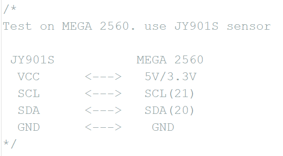
How to wiring
First prepare WitMotion standard sensor, here we take JY901S as an example and MEGA-2560 development board. Please check the below wiring:
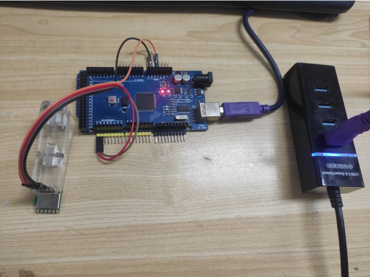
Physical wiring diagram:
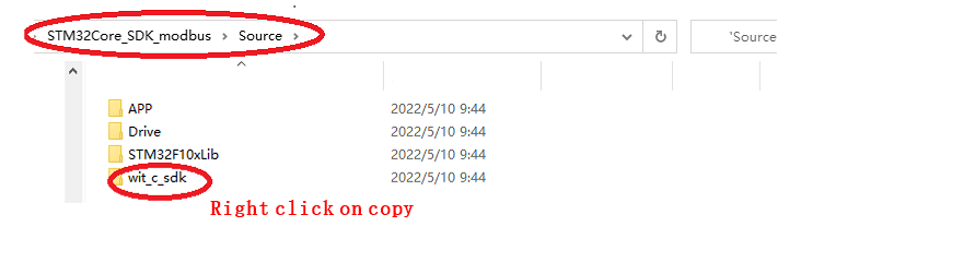
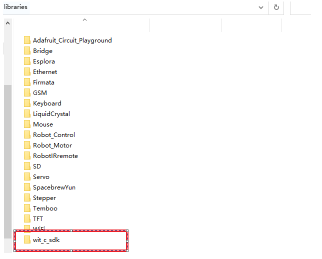
Copy the file wit_c_sdk to the library folder of Arduino's libraries
Path:STM32Core_SDK_IIC\Source
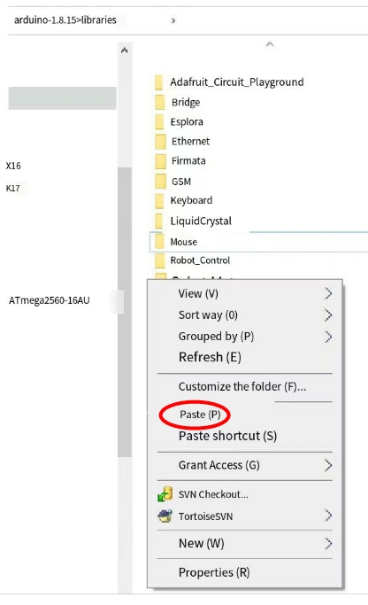
Paste path:arduino-1.8.15\libraries
After pasting successfully:
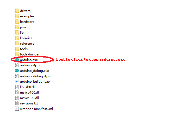
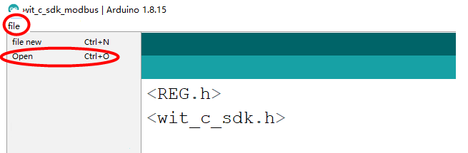
Use the Arduino software to download the program to the development board
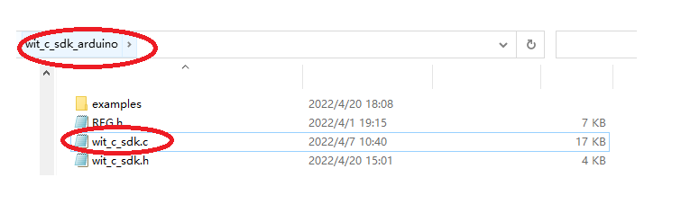
Path:wit_c_sdk_arduino\examples\wit_c_sdk_iic
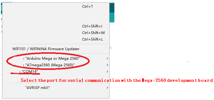
Selection of development boards, processors, and serial ports
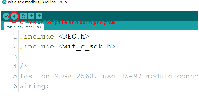
Upload and burn program
Selection of development boards, processors, and serial ports
Upload and burn program
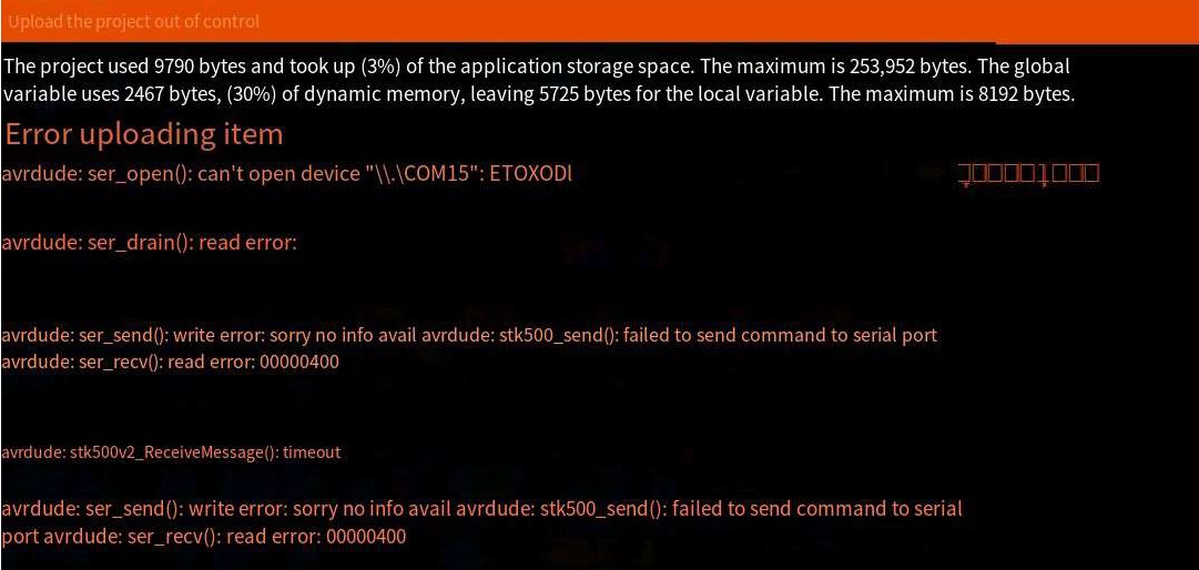
Reason for uploaded item error:
The serial port selection is wrong, the serial port is not selected, or the serial port is occupied
The above prompts show that the program is successfully compiled and downloaded to the development board.
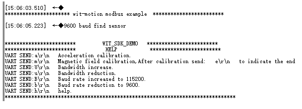
Open the serial port debugging assistant and power on again, the following information will be displayed:
You can send corresponding instructions to configure the module through the prompt information.
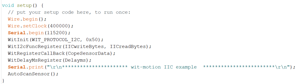
Initialization
Modules with standard protocols only need to be connected to power and serial lines, and the data will be automatically returned。
For the introduction of API functions, please read the WIT_C_SDKAPI function documentation.
Wire.begin(); //Initialize the wire library and join the I2C network
Wire.setClock(400000); //Set the transmission rate of IIC
Serial.begin(115200); //Initialize the print data serial port
WitInit(WIT_PROTOCOL_I2C, 0x50); //Initialize the IIC protocol and set the device address
WitI2cFuncRegister(IICwriteBytes, IICreadBytes); //IIC function registration
WitRegisterCallBack(CopeSensorData); //Register to get the sensor data callback function
WitDelayMsRegister(Delayms); //Register millisecond delay function
AutoScanSensor(); //Automatically search for sensors
Receive sensor data
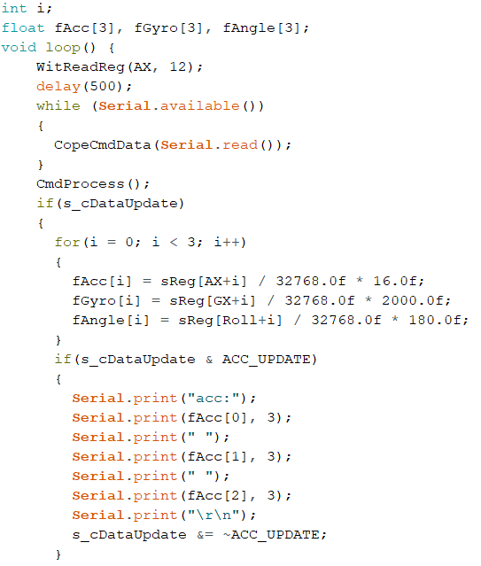
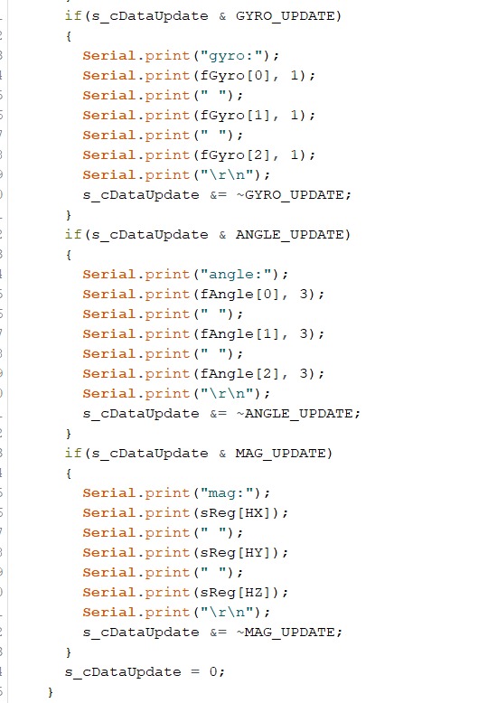
Get data
We will create an array to store the read data into the array, and read the corresponding data directly according to the index. If the module automatically lasts data, the status data update will read the data returned by the sensor, and the final effect is to read the data of the module's 3-axis acceleration, 3-axis angular velocity, 3-axis angle, and 3-axis magnetic field into the specified index array. Finally print it out. In addition, IIC needs to actively read sensor data, so it needs to access the module at intervals.
WitReadReg(AX, 12); //Interval read sensor data
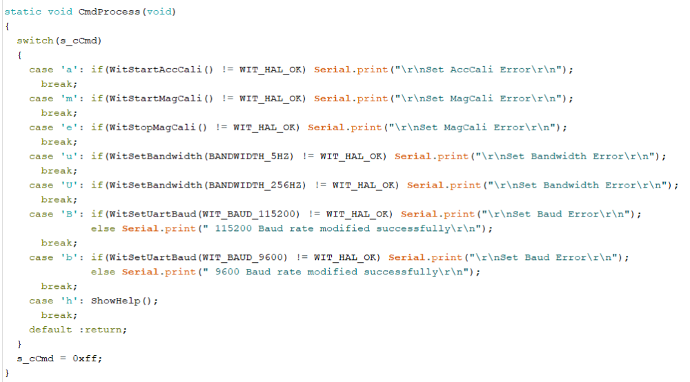
Setting sensor
The parameters of the module can be set through the function CmdProcess(); Such as acceleration calibration, magnetic field calibration and modifying baud rate etc.
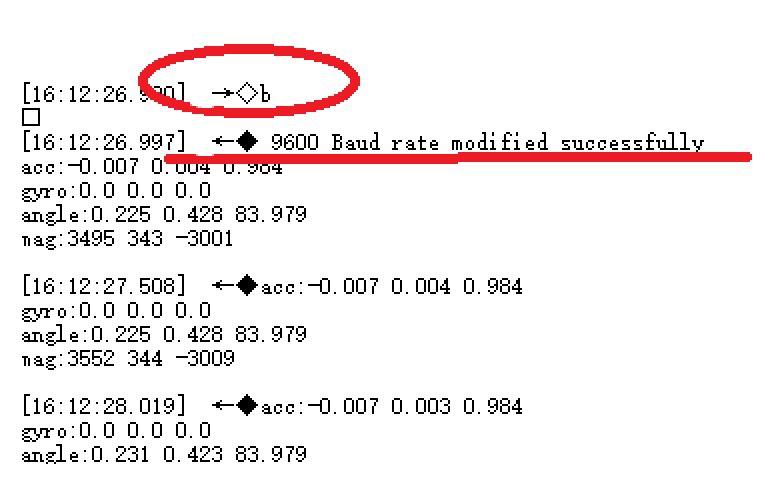
Open the serial port assistant, send the command b\r\n, and then observe the phenomenon.
Note: Be sure to check in the serial port assistant software and press Enter to change the line
After sending b\r\n, the module will search for the device again, and prompt what baud rate is found. The window displays information prompting that the 9600 baud rate search is successful, and compares the sending instructions described in the HELP prompt information. The baud rate indicates that the setting is correct. Use other commands as needed.
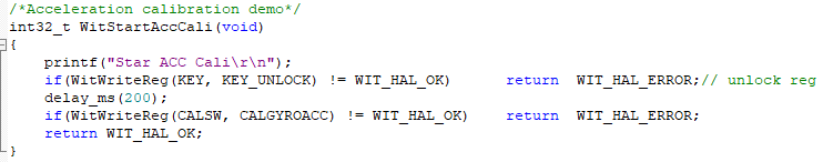
Accelerometer Calibration
file path prompt:
Some common API function interfaces are defined in the file wit_c_sdk.c, which only needs to be called.
Magnetic Calibration
file path prompt
The magnetic field calibration needs to be sent to start the calibration first, then rotate around the three axes of the sensor and then end the calibration. First call WitStartMagCali(); to start magnetic field calibration, then rotate the sensor on three axes, and then call WitStopMagCali(); to end the calibration.
More
Please reference to the sensor datasheet.
Last updated