Arduino_SDK Quick start
Arduino_SDK quick start
Applicable Model
Routine download
Go to the link below to download the sample
https://github.com/WITMOTION/WitStandardModbus_WT901C485
Routine introduction
This routine introduces how to use the serial port 1 of the MEGA-2560 platform to connect the HW-97 module and then perform Modbus protocol with the serial port of WITMOTION sensor, and then directly print data through the serial port, receive sensor data and communicate with the sensor;
Before viewing this routine, please read the relevant sensor manual to understand the protocol used by the sensor and the basic functions of the sensor
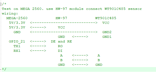
Equipment wiring
First of all, prepare WITMOTION 485 series sensors, a 485 to TTL level module, MEGA-2560 development board and a serial port three-in-one module. Wiring:
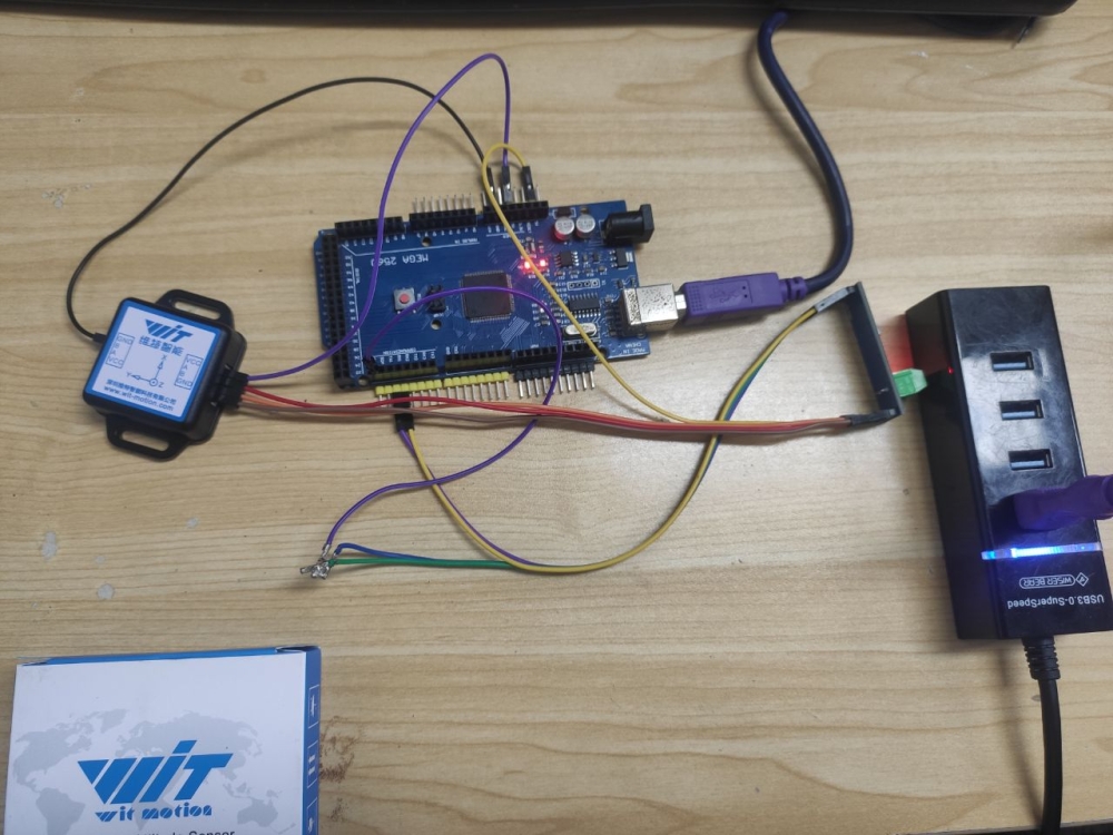
Physical wiring diagram:
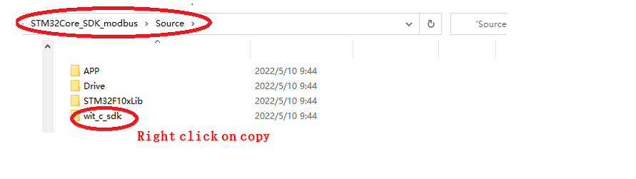
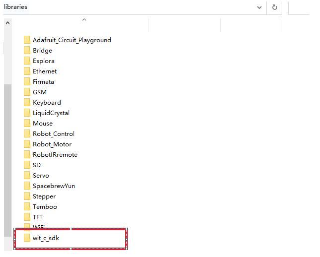
Copy the file wit_c_sdk to the library folder of Arduino's libraries
Path:STM32Core_SDK_modbus\Source
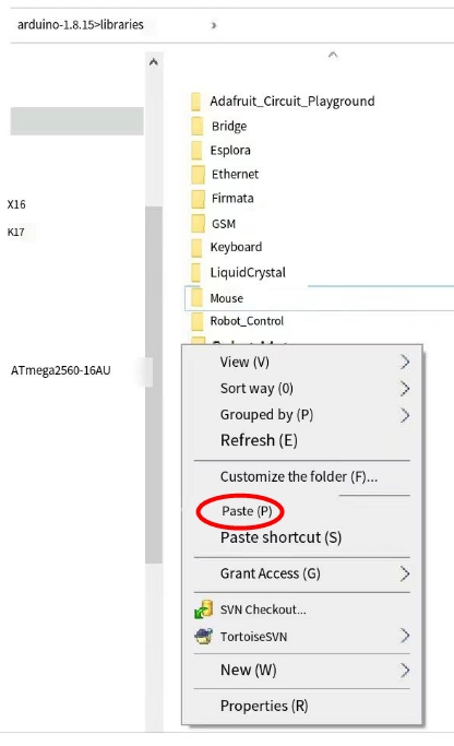
Paste path:arduino-1.8.15\libraries
After pasting successfully:
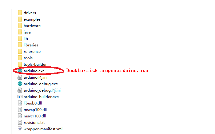
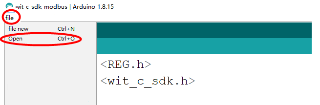
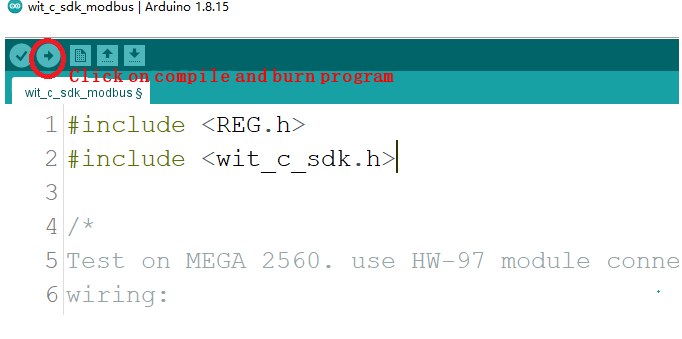
Use the Arduino software to download the program to the development board
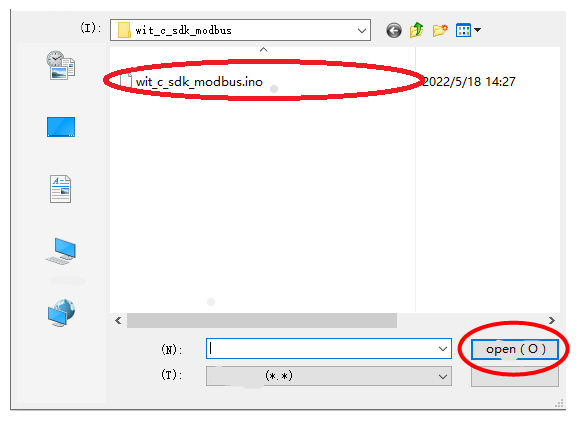
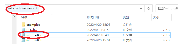
Path:wit_c_sdk_arduino\examples\wit_c_sdk_modbus
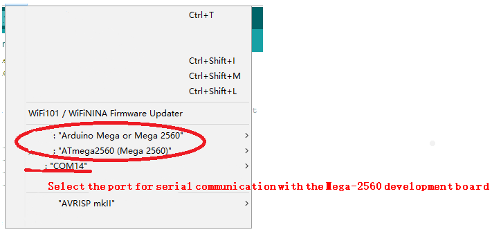
Selection of development boards, processors, and serial ports
Upload and burn program
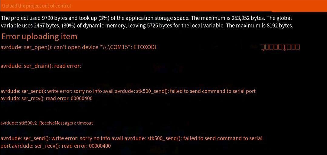
Reason for uploaded item error:
The serial port selection is wrong, the serial port is not selected, or the serial port is occupied
The above prompts show that the program is successfully compiled and downloaded to the development board.
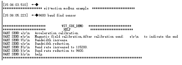
Open the serial port debugging assistant and power on again, the following information will be displayed:
You can send corresponding instructions to configure the module through the prompt information.
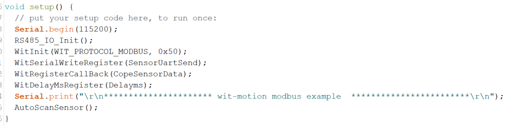
Initialization
Modbus is a one-question-one-answer interactive form, so the module needs to be continuously inquired before the data can be returned.
For the introduction of API functions, please read the WIT_C_SDKAPI function documentation.
Serial.begin(115200); //Initialize the print data serial port
RS485_IO_Init(); //485 Pin Configuration Initialization
WitInit(WIT_PROTOCOL_MODBUS, 0x50); //Initialize the modbus protocol and set the device address
WitSerialWriteRegister(SensorUartSend); //Register write callback function
WitRegisterCallBack(CopeSensorData); //Register to get the sensor data callback function
WitDelayMsRegister(Delayms); //Register millisecond delay function
AutoScanSensor(); //Automatically search for sensors
Receive sensor data
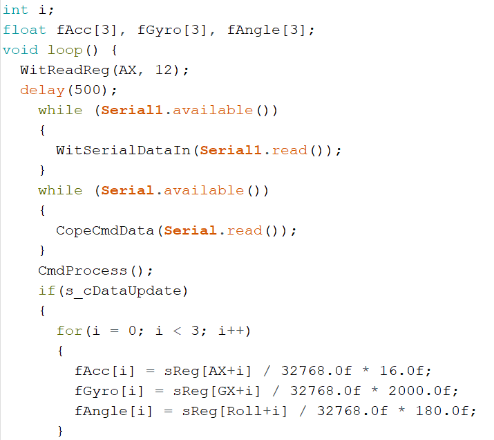
Get data
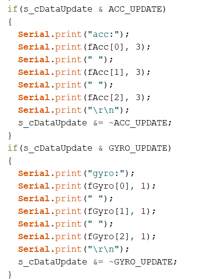
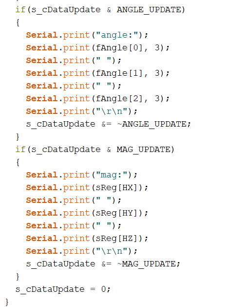
We will create an array to store the read data into the array, and read the corresponding data directly according to the index. Since the module used this time is the modbus protocol, when you need to ask, you need to provide the data start address and the amount of data to be read. For example, the example calls WitReadReg(AX,12) every 500ms; the starting address is AX (acceleration X value) to read 12 data continuously, and the final effect is to read the 3D acceleration, 3D angular velocity, 3D angle, and 3D magnetic field of the module. The data into the specified index array. Finally print it out.
WitReadReg(AX, 12);//interval reading module, the address starts from AX (acceleration X) to read 12 bytes of data. Refer to REG.H register list
Set sensor
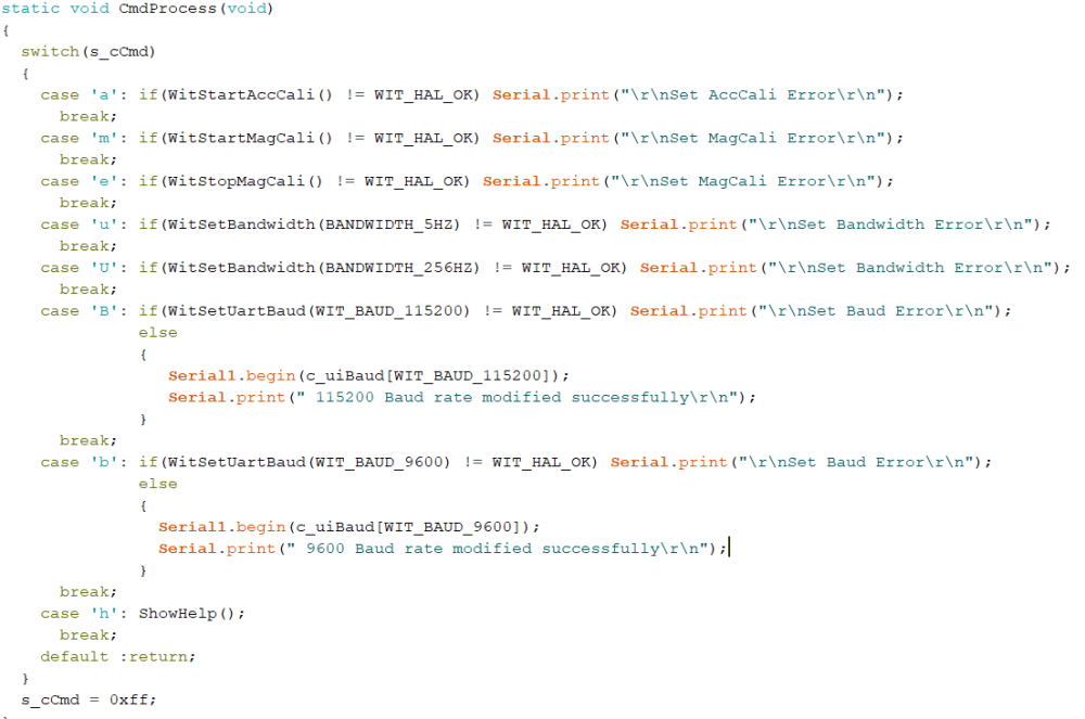
The parameters of the module can be set through the function CmdProcess(); Such as acceleration calibration, magnetic field calibration and modifying baud rate, etc.
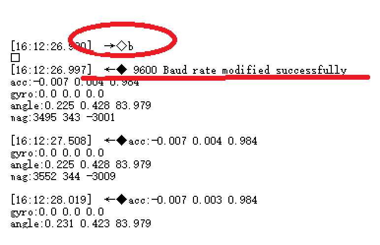
Open the serial port assistant, send the command b\r\n, and then observe the phenomenon.
Note: Be sure to check Add Carriage Return and Line Feed in the serial port assistant software
After sending b\r\n, the module will search for the device again, and prompt what baud rate is found. The window displays information prompting that the 9600 baud rate search is successful, and compares the sending instructions described in the HELP prompt information. The baud rate indicates that the setting is correct. Use other commands as needed.
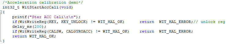
Accelerometer Calibration
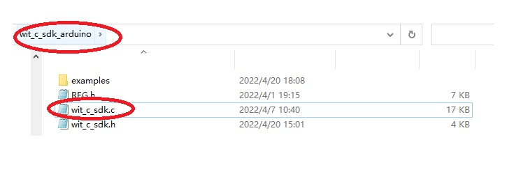
File path hint:
Some common API function interfaces are defined in the file wit_c_sdk.c, which only needs to be called.
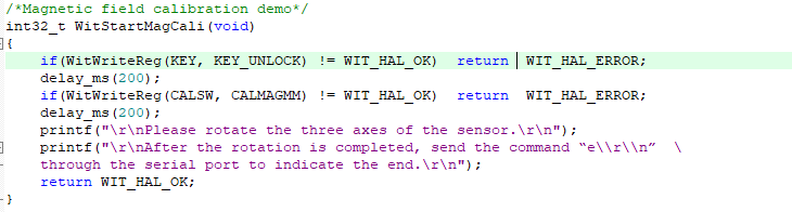
Magnetic Field Calibration
file path prompt
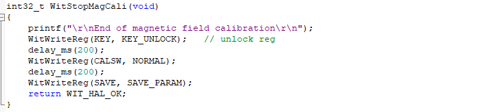
The magnetic field calibration needs to be sent to start the calibration first, then rotate around the three axes of the sensor and then end the calibration. First call WitStartMagCali(); to start magnetic field calibration, then rotate the sensor on three axes, and then call WitStopMagCali(); to end the calibration.
More
For other operations, please refer to the SDK manual
Last updated