Python_SDK Quick start
Python_SDK Quick start
Applicable Model
Routine download
Go to the link below to download the sample
https://github.com/WITMOTION/WitStandardModbus_WT901C485
Noun introduction
Modbus protocol: Usually 485 sensors use this protocol; the sensor of this protocol will not actively upload data, here it is necessary for the host computer to send instructions to obtain
Protocol description
Read instruction format: ID (1 byte) + 0x03 + start register (2 bytes) + number of registers (2 bytes) + CRC check (2 bytes). A total of 8 bytes, the returned data must start with ID + 0x03 + data length + data, and the last two bytes are CRC check.
Write instruction format: ID (1 byte) + 0x06 + register (2 bytes) + value (2 bytes) + CRC check (2 bytes). A total of 8 bytes.
Routine introduction
This routine introduces how to use Python to develop the upper computer to connect to the WITMOTION protocol sensors, receive sensor data, and communicate with the sensors; Before viewing this routine, please read the relevant sensor manually to understand the protocol used by the sensor and the basic functions of the sensor
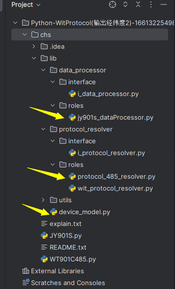
Routine directory
The figure below is the routine directory, and the arrows indicate the files that need to be referenced
Initialize the device
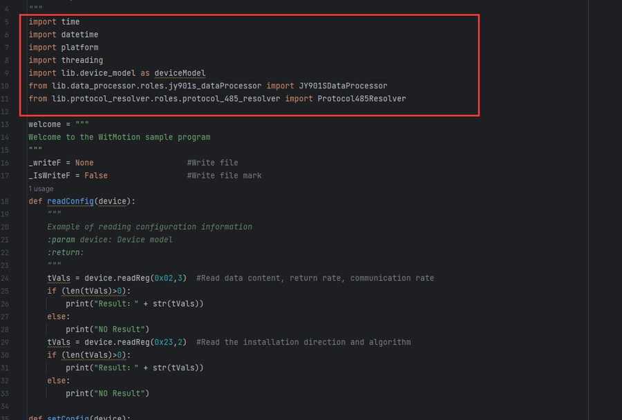
Open the WT901C485.py file and import the file in the above picture as shown in the figure:
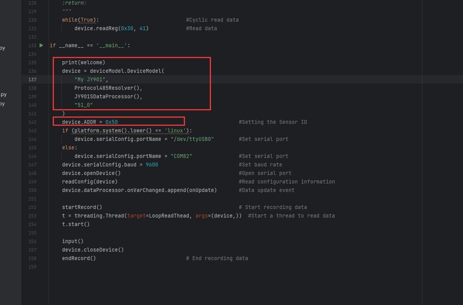
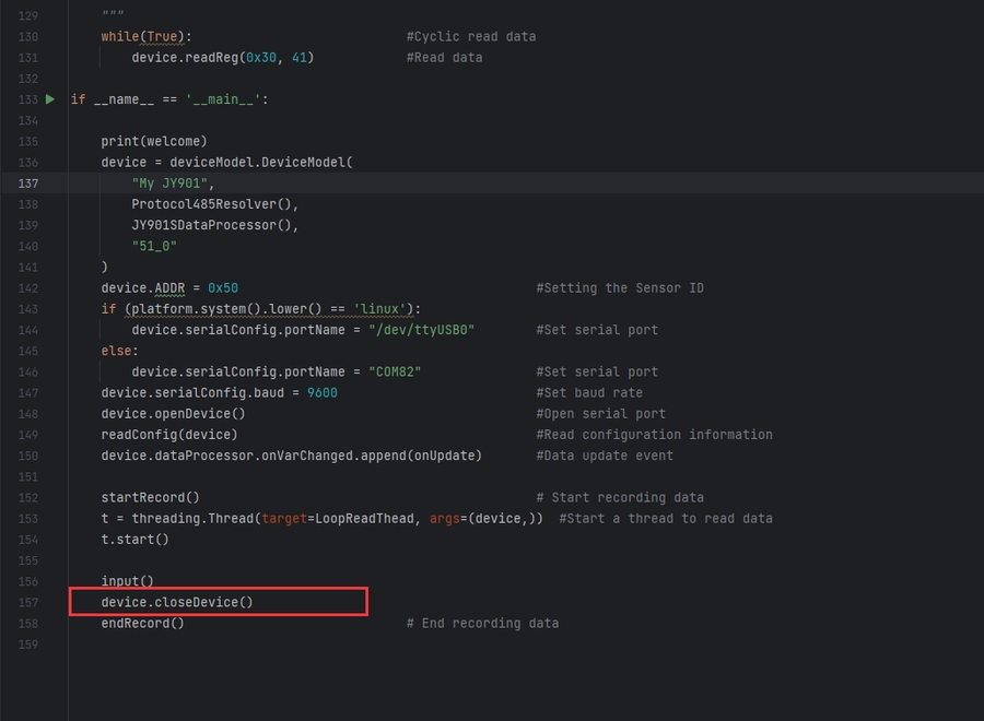
In if__name__ == '__main__': The device model is initialized here, and the protocol and data processing method used are specified. And the callback method when the sensor data is updated, as shown in the figure:
DeviceModel (device model): The DeviceModel object represents the sensor in the program and can interact with the sensor data. This object will automatically calculate the sensor data. How to obtain the sensor data through the DeviceModel object will be introduced later.
Note that there is an additional sensor ID configuration here. If this item is incorrect, the program cannot communicate with the device.
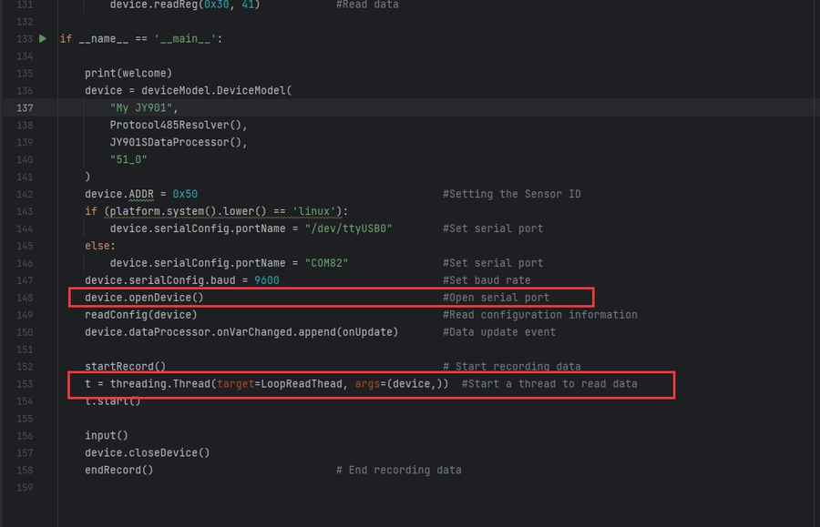
Turn on the device
Open the device and directly call the openDevice() method of the device model, as shown in the figure
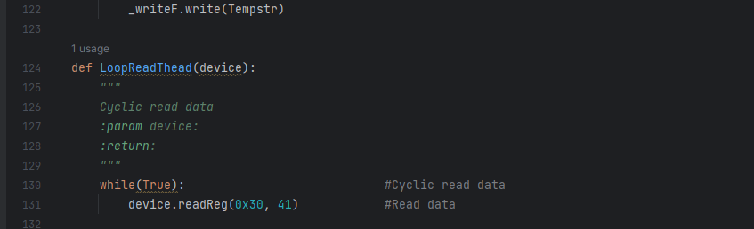
Since the Modbus protocol needs to issue instructions to return data, this example program uses a thread to issue instructions to obtain data. As shown in the above figure, the thread calls the LoopReadThead() method, as shown in the figure below:
Turn off the device
Close the device and directly call the closeDevice() method of the device model, as shown in the figure
Receive sensor data
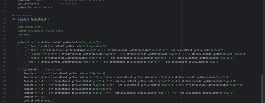
Since the device model settles the sensor data, we only need to obtain the data in the onUpdate method, as shown in the following figure:
Record data
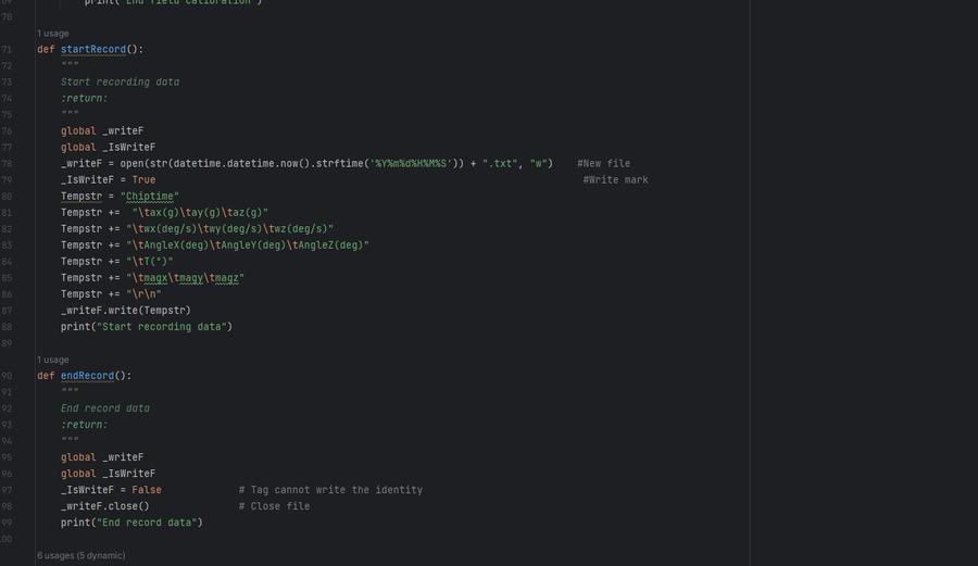
Call the startRecord() method in the current file to start recording, then get the data in the onUpdate method according to the write flag, and write it to the file
Finally, call the endRecord() method to end the record and close the file. As shown below:
Read sensor configuration
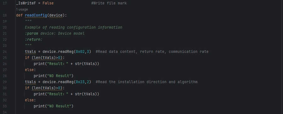
After opening the device, you can call the readConfig(device) method to obtain configuration information, as shown in the figure below:
To read the configuration information of a register, the function readConfig(regAddr,regCount) of the device model can be called.
The first parameter of this function regAddr: the starting register address;
The second parameter regCount: the number of registers (note that there must be consecutive register addresses). As shown above: 0x02=data content; 0x03=return rate; 0x04=communication rate. So calling device.readReg(0x02,3) returns the corresponding value as shown below:
For other configuration information, please refer to the sensor manual
Set sensor configuration
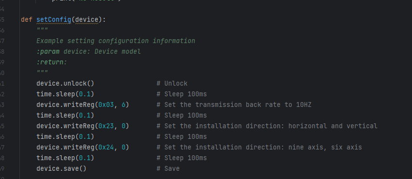
After opening the device, you can call the setConfig(device) method to set the configuration information, as shown in the figure below:
To set the value of a register, call the writeReg(regAddr,sValue) method of the device model. This method has two parameters: the first parameter: register address; the second parameter: the written value.
Calling steps: unlock -> write register -> save
Note: When writing multiple registers, there must be a certain interval (usually 50~100 milliseconds)
Please refer to the sensor manual for setting other configuration information
Accelerometer Calibration
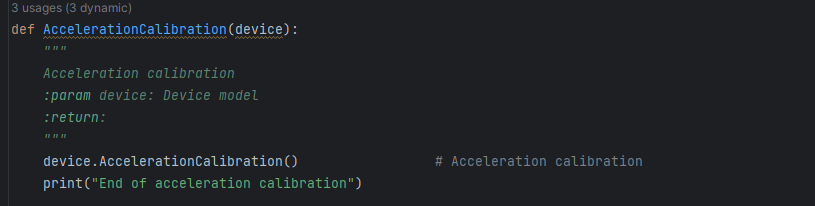
After turning on the device, you can call the AccelerationCalibration() method of the device model to calibrate the accelerometer, as shown in the figure below:
It takes more than 5 seconds to execute this method
Magnetic Field Calibration
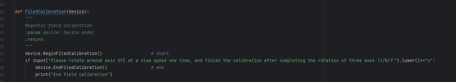
After turning on the device, magnetic field calibration requires three steps:
You can call the BeginFiledCalibration() method of the device model to start calibration
Please rotate slowly around the XYZ axis respectively
Call the EndFiledCalibration() method of the device model to end the calibration, as shown in the figure below:
Precautions
💡If the serial port number, volatility, and sensor ID set by the user are incorrect, the sample program will not be able to receive data normally!
Last updated