STM32_SDK Quick Start
STM32_SDK Quick Start
Applicable Model
Routine download
Go to the link below to download the sample
https://github.com/WITMOTION/WitStandardCAN_HWT905CAN
Routine introduction
This routine introduces how to use STM32Core platform serial port 2 to connect WitMotion serial port 485 protocol, and then directly print data through serial port 1, receive sensor data and communicate with the sensor;
Before viewing this routine, please read the relevant sensor manual to understand the protocol used by the sensor and the basic functions of the sensor
Equipment wiring
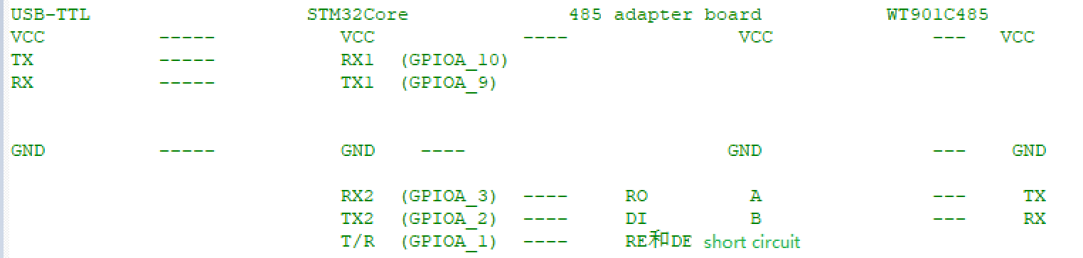
First of all, prepare WitMotion 485 series sensors, a 485 to TTL level module, STM32Core development board and a serial port three-in-one module. Wiring:
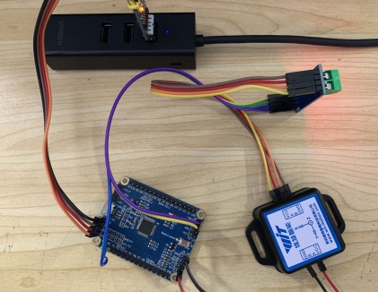
Physical wiring diagram:
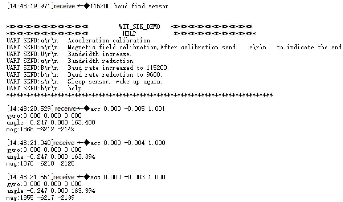
Download the program to the development board, open the serial port debugging assistant at the same time, and power on again, the following information will be displayed:
You can send corresponding instructions to configure the module through the prompt information.
Initialization
Modbus is a one-question-one-answer interactive form, so the module needs to be continuously inquired before the data can be returned.
For the introduction of API functions, please read the WIT_C_SDKAPI function documentation.
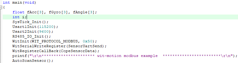
Usart1Init(115200);//Initialize the print data serial port
Usart2Init(9600);//Initialize the serial port connected to the module
RS485_IO_Init();//Initialize the half-duplex 485T/R control pin
WitInit(WIT_PROTOCOL_MODBUS, 0x50);//Initialize modbus protocol, set device address
WitSerialWriteRegister(SensorUartSend);//register write callback function
WitRegisterCallBack(CopeSensorData);//Register to get sensor data callback function
AutoScanSensor();//Search sensor automatically
Receive sensor data
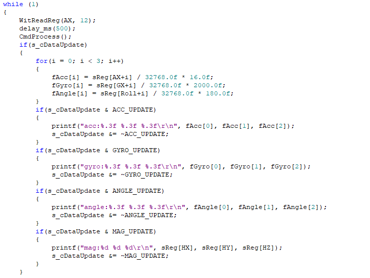
Get data
We will create an array to store the read data into the array, and read the corresponding data directly according to the index. Since the module used this time is the modbus protocol, when you need to ask, you need to provide the data start address and the amount of data to be read. For example, the example calls WitReadReg(AX,12) every 500ms; the starting address is AX (acceleration X value) to read 12 data continuously, and the final effect is to read the 3D acceleration, 3D angular velocity, 3D angle, and 3D magnetic field of the module. The data into the specified index array. Finally print it out.
WitReadReg(AX, 12);//interval reading module, the address starts from AX (acceleration X) to read 12 bytes of data. Refer to REG.H register list
Set sensors
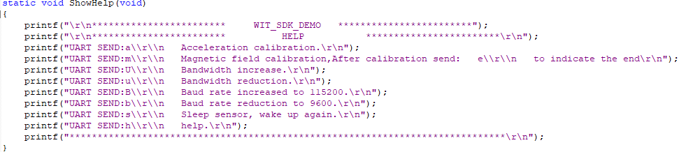
The parameters of the module can be set through the function CmdProcess(); Such as acceleration calibration, magnetic field calibration and modifying baud rate, etc.。
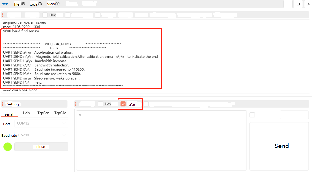
Open the serial port assistant, send the command b\r\n, and then observe the phenomenon.
After sending b\r\n, the module will search for the device again, and prompt what baud rate is found. The window displays information prompting that the 9600 baud rate search is successful, and compares the sending instructions described in the HELP prompt information. The baud rate indicates that the setting is correct. Use other commands as needed.
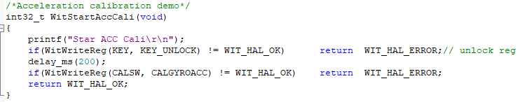
Accelerometer Calibration
Some common API function interfaces are defined in the file wit_c_sdk.c, which only needs to be called.
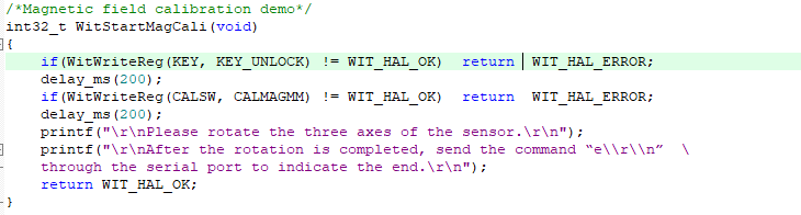
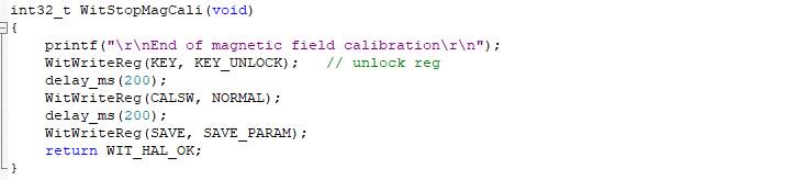
Magnetic Field Calibration
The magnetic field calibration needs to be sent to start the calibration first, then rotate around the three axes of the sensor and then end the calibration. First call WitStartMagCali(); to start magnetic field calibration, then rotate the sensor on three axes, and then call WitStopMagCali(); to end the calibration.
More
其它操作请参考SDK说明书
Last updated