PLC_Mitsubishi reads modbus protocol
PLC_Mitsubishi reads modbus protocol
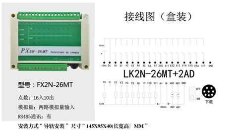
Applicable Model
Directory navigation:
(1)——环境搭建
(2)——单传感器单角度报警
(3)——传感器校准
(4)——多传感器多角度报警
Background introduction
Recently, due to the needs of the project, it is necessary to use PLC to obtain the tilt angle of the equipment and send out an alarm. After careful research and research, the PLC has chosen a domestic Mitsubishi-compatible PLC, which is more cost-effective.
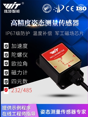
There are many sensors available in the market, but there are not many manufacturers that support the Modbus protocol of PLC, and I use it in an industrial environment, which is good for stability and small temperature drift. After a comprehensive comparison, we chose the HWT905 of WITMOTION, which uses an industrial-grade sensor chip with temperature compensation. The magnetic field chip uses the highest-precision PNI magnetic field sensor on the market, which has excellent anti-interference and stability. The Kalman filter algorithm is used to fuse information from the accelerometer, gyroscope, and magnetic field to obtain more accurate data.
The main parameter performance of the sensor is as follows
Voltage: 5V~36V
Current: <40mA
Volume: 55mm X 36.8mm X 24mm
Measurement dimensions: acceleration: 3D, angular velocity: 3D, magnetic field: 3D, angle: 3D
Range: acceleration: ±6g, angular velocity: ±2000°/s, angle ±180°.
Stability: acceleration: 0.01g, angular velocity 0.05°/s.
Measurement error: X Y axis 0.05°, Z axis 1° (the magnetic field is well calibrated and not disturbed by the magnetic field).
Data output content: time, acceleration, angular velocity, angle, magnetic field.
The data output frequency is 0.2Hz~200Hz.
Data interface: serial port (485 level, baud rate supports 4800, 9600 (default), 19200, 38400, 57600, 115200, 230400, 460800, 921600).
Precautions:
It needs to be installed in the root directory of the C disk, and the default path is fine, otherwise it will not be installed normally. Steps
Steps:
1、Open the software GX Works2 and click Project. [MISSING IMAGE: , ]
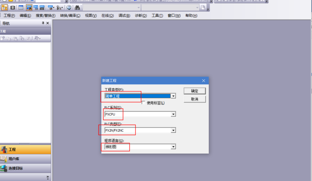
2、Click New Project, set the parameters, and click OK.
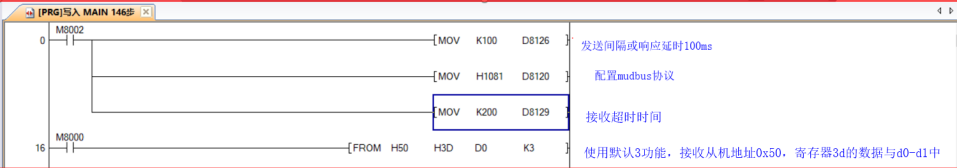
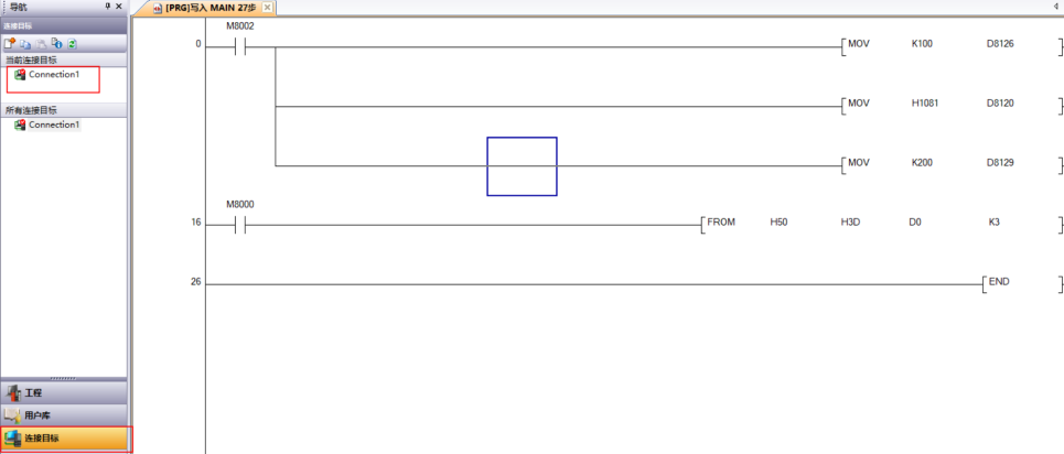
3、Write the following command, the last command is gray, this is the reason for no conversion, click convert/compile, convert. 】[MISSING IMAGE: , ]
4、Connect the plc to the power supply, connect the plc and the computer with the usb-sc09-fx cable, and click the connection target in the box.
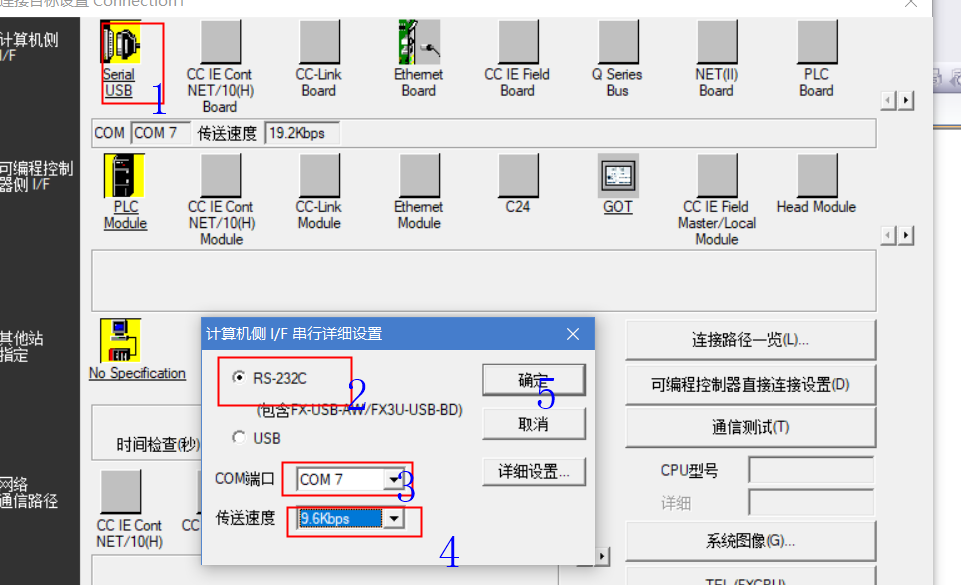
5、As shown in the figure below, click the Serial USB in the box to configure the communication;
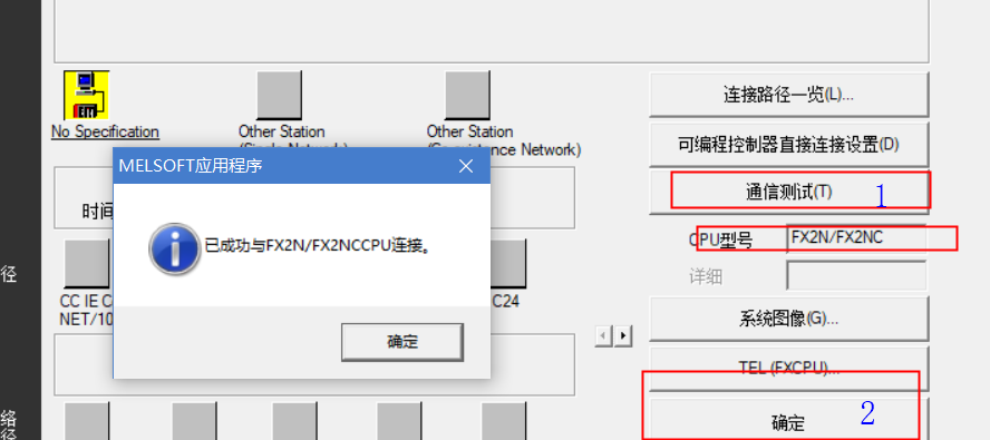
6、After the configuration is complete, click the communication test. If the PLC is connected normally, it will prompt a successful connection, and the cpu model will be displayed, and then click OK. If there is no confirmation, the configuration will not be successful.
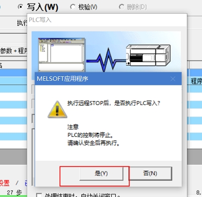
7、As shown in the figure below, click Online, then click Write, select Write, select See+Program and click Execute to program the PLC.
As shown in the figure below, there will be such a window prompt during the programming process, click Yes.
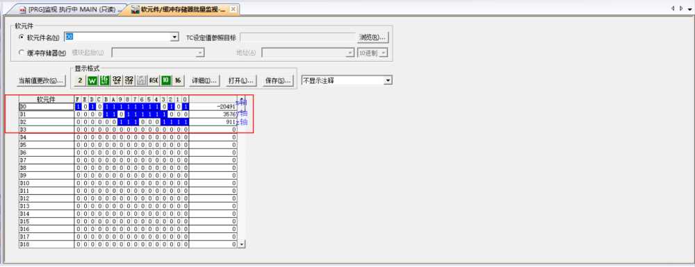
8、Click box 1 to monitor and control the plc, click box 2 to open batch monitoring of the device buffer memory, enter D0 in the device name, and check the data of the register (D0 is the original data of the x-axis, D1 is Raw data for the y-axis, D2 is the raw data for the z-axis). [MISSING IMAGE: , ]
Last updated